| |
| |
From version 1.8.6.4 MagicQ includes an advanced colour picker system able to mix colour using all available emitters of any colour-mixing fixtures, including those with extended emitter sets (amber, lime, UV, etc).
To perform this task accurately, the colour picker relies upon colourimetry data (see section below), provided by the fixture manufacturer. If this is not available, an estimate is used which reduces the accuracy of colour matching.
Colourimetry data can also be provided by the user; to do this, refer to Adding colourimetry data to a head
A number of different models exist to define individual colours; the most commonly used by colour-mixing fixtures are red-green-blue (RGB), cyan-magenta-yellow (CMY), with some including a mode for hue-saturation-intensity (HSI) as well. These are all examples of colour spaces, an abstract model for describing colours as a set of three (or more) values.
One limitation of the above models is that they are defined based on a set of primary colours, which may vary between devices (for example, how red is the "red" in RGB?). For this reason, colour scientists use a more general model to describe colours: CIE 1931. This measures the colour of a light source using two coordinates, x and y, and the brightness with a third, Y (capital).
These coordinates are independent of any device, and form a three-dimensional space of potential colours. Note that not all combinations of x and y are real colours perceivable by the human eye. Points outside of the horseshoe shape of a CIE chart correspond to colours that could be "seen" if specific signals were given to the brain, but these signals can never be given by the human eye (under normal circumstances). These are "impossible" or "forbidden" colours, and they exist only theoretically. Under HSI models, they can be thought of as colours with over 100% saturation.
One advantage of CIE 1931 is that mixing any two colours on a CIE chart will produce a colour along the straight line that joins them (unfortunately, an equal mix is not guaranteed to be in the middle).
The RGB colourspace used in the colour picker is sRGB; this is the space of colours that can be displayed by most computer screens. It should be noted that these channels do not directly control the red, green, and blue emitters of a fixture; they may be able to display deeper colours than sRGB can produce.
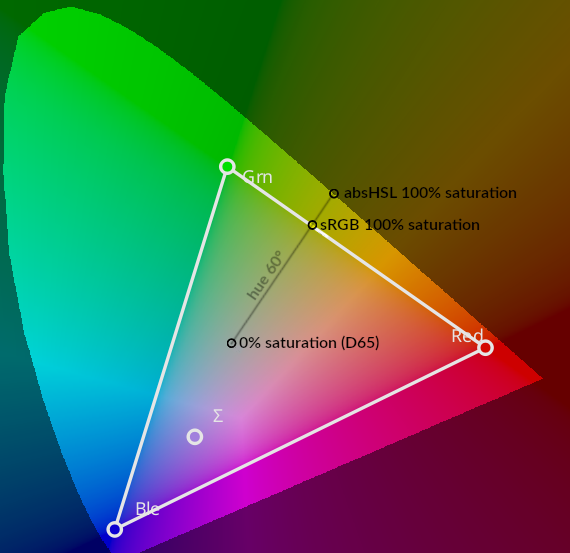
The HSL colourspace used is an extension of the sRGB HSL space. It will be referred to here as "AbsHSL". The definition of "hue" is the same in both systems, as is the definition of "0% saturation" as being 6500K white. However, AbsHSL saturation extends all the way to the edge of the space of possible colours. This is the same as the concept of "excitation purity" in colour science (with a white point of D65).
For example, under sRGB, "Yellow" is usually defined as: hue 60°, saturation 100%. Under AbsHSL, this same colour is still hue 60°, but has a saturation of only 79%. The image below shows the difference between the two in CIE 1931 space (with sRGB overlaid). Note the straight line representing hue 60° in both systems.
The CCT colour space uses correlated colour temperatures. The two values are temperature (in Kelvin), and Delta-UV, (in UV units).
As objects are heated, they begin to glow different colours. The temperature of a "white" colour is defined as what temperature an object would need to be heated to start giving off that colour. For instance, heating an object to about 6500K will cause it to glow a bright white; the colour of a clouded sky. The colours that can be achieved this way fall along a curved line in CIE 1931 space, called the "Plankian locus".
The delta-UV value is used to produce colours other than "whites". This measures the distance from the Plankian locus in a different CIE colourspace (CIE UV), either upwards (positive values) or downwards (negative). The practical effect of this is that a positive delta-UV is similar to "add green", and a negative is "subtract green", similar to colour gels made for the same purpose. Using this channel allows for reds, oranges, yellows, pale greens, pinks, and purples to be achieved.
There is a rough correspondence between plus/minus green gels and delta-UV; a one-eighth gel is about 0.004 UV, a one-quarter gel is about 0.008 UV, and so on.
This colourspace cannot produce deep blues or cyans. This is because no matter how hot an object is heated, it will never give off saturated blue light; the temperature axis ends at "infinity kelvin", which is a deep sky blue colour.
You can measure a light source (such as a fixture) to determine the exact colours each emitter gives off; this process is called colourimetry.
From these colours, one can determine the range of all possible colours that a light source can give; this is called that source’s "gamut". Plotted in 3D CIE 1931 space, this forms a roughly polyhedral shape; all colours inside this shape can be made. The bottom surface (Y=0) is all black; the very peak of this shape is the source’s "white" - which you get if you have all the emitters set to 100%. The Y axis is scaled to the luminosity of this white, so it is always at Y=1.
To illustrate, below is a representation of all the colours that can be produced by a normal sRGB computer monitor. Note the corners that can be seen for the red and blue emitters (green is at the back), and again for cyan, magenta and yellow. Green is the brightest emitter by far, and so cyan and yellow have a very high luminosity compared to magenta.
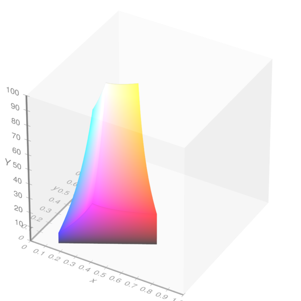
Michael Horvath (SharkD), Christoph Lipka / Wikimedia Commons / CC BY-SA 4.0
The different meanings of "brightness" and "luminosity" should be noted carefully.
Luminosity is the scientific measure of the intensity of a light source, regardless of its colour; it can be measured with a light meter, giving a value in lux.
"Brightness", on the other hand, has no strict definition. The definition used by the colour picker is dependent on a particular fixture’s gamut. If one thinks of the three-dimensional gamut shape above, the "floor" (Y=0) represents both 0% brightness and 0 luminosity. The "ceiling" of that shape represents 100% brightness; these are the brightest versions of all the colours that the fixture can make. If one sets the colour picker to a certain colour (e.g: x=0.625, y=0.314), and the brightness to 50%, this means "50% as bright as the brightest colour that can be produced with (x=0.625, y=0.314)".
One challenge to colour matching is that finding the shape of this "ceiling" is a difficult process. MagicQ approximates it’s shape by modelling it as a set of flat planes; in reality, it is somewhat concave, meaning that MagicQ may overestimate what a fixture’s brightest colours really are. This can lead to a slight loss of matching accuracy when the brightness is set very high; reducing the brightness should help if this is an issue.
The colour picker window is divided into two separate views; the colour wheel or graph on the left, and a separate set of controls on the right. If the colour picker window is too small to display both, the wheel is hidden by default; the "SHOW WHEEL" soft button is then enabled, and can be used to toggle between the wheel and the other view.
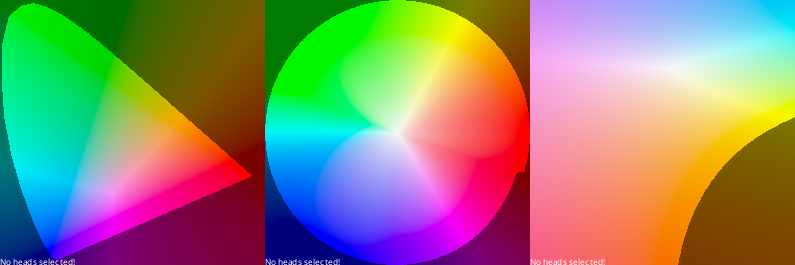
The left-hand view is a 2D representation of the colour space. This can be switched between different modes using the E soft button. This cycles through three modes: CIE 1931, a Hue-Saturation wheel, and a special chart for choosing colour-corrected whites.
The gamut of the current fixture is displayed as a white polygon; if multiple fixtures are selected, their gamuts are displayed overlaid on each other. The position of each emitter is shown as a white circle.
This gamut also shows another value, the "locate colour", which is signified with the Σ (sigma) symbol. This represents the result of turning all emitters to 100%; this is the fixture’s white point. Note that on many fixtures, this may not be anywhere near a true white.
If there is no colourimetry available for a fixture, then a white message at the bottom indicates this. In this case, a default set of colourimetry data is used depending on the fixture type. Colour values shown will be an approximation only.
In all three modes, there is a portion of the chart that represents "forbidden colours", as mentioned above. This region is shown with darkened colours to represent this. While it is possible to select colours within this region, it should be noted that no fixture - even in principle - will be able to represent these.
Clicking on the colour wheel will select the colour under the cursor. If fanning is currently active (see below), the closest fan end to the cursor will be moved to it.
The selected colour or colours are shown as black circles. If a colour fan is active, the fan ends are marked with S and E for "start" and "end", and hovering over the other circles will show their position in the fan.
Also visible sometimes are small black X marks; these appear if, for a variety of reasons, the selected colour cannot be perfectly achieved. The X shows the colour that the fixture is actually emitting.
The colour wheel mode also determines the function of the encoder wheels when the colour picker window is focused. Each encoder corresponds to one colour channel.
The faders view shows one fader for each available colour channel. The colour channels available depends on the current wheel mode; for instance, the RGB faders are not available in CIE 1931 mode, and most faders are not available in CCT mode.
The "hue" fader is not limited at it’s ends. Dragging the fader beyond it’s limits will cause it to wrap around from the other side.
The fader tracks show the colours that will be selected if the fader is moved along it’s range. If these colours are outside of the fixture’s gamut, they are shown darkened. If the colour is completely impossible, the fader track is black.
The faders can also be used to directly set a value; to do this, type in a number on the command line and click on the fader. For instance, to set the colour temperature to 6500K, type "6500" and click on the temperature fader.
Since version 1.9.5.4, there is a Mix fader. This fader only takes affect when you are using LED fixtures with four or more emitters and the brightness fader is not set to 100%. Moving this fader changes the output of emitters while maintaining the same colour. You can see the effect of this in the outputs window.
There are also three selection modes which determine how the colours influence the colour of the selected fixtures:
The simplest mode, all fixtures and their fixture elements are set to the selected colour, if possible. If different types of fixtures are selected, the DMX values of each one will be set so that the closest possible representation of the selected colour is achieved.
This mode is for creating colour fans. The currently chosen colour is interpreted as being the START of the fan. Selecting a new colour (by any method) will choose the end of the fan. Once a fan is selected, you can use the SELECTED START / SELECTED END soft button to choose which end is adjusted by the faders. Clicking on one of the ends in the colour wheel will also change this.
The colours will fan across the channels that were adjusted. If you use a fader to create a fan, the colours will be distributed across that fader’s colour channel; for instance, if the hue fader was used to fan 7 fixtures from 0° to 60°, their hues will be 0°, 10°, 20°…50°, 60°.
If the colour wheel is used, then the fixtures will fan across the channels represented by the wheel: in CIE mode, this is CIE x and y, and in HSL mode, this is hue and saturation.
By default, all fans are symmetrical; they go to the target colour, and back again. Pressing FAN TYPE SYMMETRIC / FAN TYPE LINEAR will toggle between this and linear mode, where the first fixture has the start colour, and the last fixture has the end colour. Note that changing this option once a fan is already in progress may cause strange results.
When in "SELECT RELATIVE" mode, the faders change function to adjust the colours already in the colour picker. For instance, if one already has a colour fan set up, one can use the saturation fader to make this fan smoothly fade to white. This can also be used to adjust the colour temperature of a set of colours (in an approximate way) by using the colour temperature fader.
| | ||