| |
| |
The Head Editor is accessed from the Edit Head soft button in the Patch Window. Making changes modifies the head files stored on the MaqicQ hard drive and used for all new shows.
The Head Editor consists of 5 views for modifying data:
In each of the views new values can be entered using the keypad or keyboard. New entries can be added to the lists by pressing the Insert soft button. The top right encoder wheel can be used to modify the item where the cursor is placed.
The Head Editor will start up with the chosen head - i.e. the last head you chose for patching. If you have not yet chosen a head then the Head Editor will be empty.
You can choose the head to edit from within the Head Editor by pressing the Choose Head button. This has the same effect as the Choose Head button in the Patch Window - i.e. you are presented with a list of heads to choose from.
Once you have made modifications to the head you can save the changes to disc by pressing the SAVE HEAD soft button.
If you wish to create a new head from scratch you can press the New Head soft button, whilst if you wish to copy an existing head you can use the Save As soft button.
At any time you can choose a new head - however if you have made changes, which you have not saved to disc, then you will be prompted whether you really wish to continue. Continuing will mean that the changes will be lost unless you already have patched heads of that type - in which case the patched heads in the show will keep the changes. In either case, the head file on the disc will not keep the changes.
Press the Patch button to leave the Head Editor and return to the Patch Window.
MagicQ stores heads in the show/heads folder. When you choose a head to use in a show it loads the head and stores it in memory.
When you save your show, MagicQ writes a copy of the head into the show file, ensuring that your show will work even if it is loaded onto a console which does not have the head files for your chosen heads installed.
If you load an old show into MagicQ then the heads in use on the show will be the ones recorded into the show file, not the heads in the show/heads folder on the MagicQ console. From the Patch Window, if you choose the head again, edit the head, or patch new heads of the same head type it will always use the head stored in the show file – this ensures consistency.
You can update a head stored in a show file with the one stored in show/heads using the "Reload Head" soft button. In the Head Editor press the "Reload Head" soft button. The head will be reloaded from disc and all the patched heads in the show will use the updated head. Note that it is not possible to reload a head where the number of channels in the head has been changed.
From v1.9.3.3 MagicQ by default no longer expands the personality library head files from the heads.all file into the Heads folder, instead it reads library Heads direct from the heads.all file. Only Heads created or edited by users are stored in the Heads folder.
Expanding of library head files is controlled by the option Setup, View Settings, Mode, Personality File Format. The options are Original and Unexpanded.
When set to Original, MagicQ expands all the personalities from the heads.all file into the Heads folder, whenever the heads.all file is changed or software is upgraded.
When set to Unexpanded, MagicQ does not expand the heads.all file into the Heads folder. Library Heads are accessed directly from heads.all. MagicQ will remove any library Heads from the Heads folder if they were perviously expanded there.
To update MagicQ with all the latest heads, download the latest heads files (heads.all) from the ChamSys web site www.chamsys.co.uk. Copy the heads.all file into the show/heads folder. Then restart MagicQ (SHIFT + RESET in Setup Window).
To load a single head into MagicQ consoles, simply copy the head file (myhead.hed) onto a USB drive, connect to the MagicQ console and select the file via the console file manager (Setup > View Settings > File Manager) MagicQ will then automatically load the head file and recreate the head index.
To load a single head file into MagicQ PC systems use the tools menu at the top of the MagicQ window and select the Install Head File(s)) option. Once you have selected your head file MagicQ will automatically load the head file(s) into MagicQ.
To force the index file to be regenerated, go to File Manager and press SHIFT + RECREATE INDEX. New heads should then appear in Patch.
Alternatively, you can patch the head into a show file, save the show to USB, Load the show on the console, then go to Patch, put the cursor on the required head, hold SHIFT and press the EDIT CUR HEAD soft button and then press SAVE HEAD to save it to the console.
Existing heads can be modified by simply making changes and pressing SAVE. Note however that these changes may be overriden if you change software version as this loads the latest head libraries. If there are genuine errors in the head then please let us know so that we can update our libraries.
The heads in the ChamSys library are protected to avoid accidental changes to them – MagicQ prompts the user before allowing changes to the heads. In the Head Editor, original ChamSys heads are indicated by an "LO" in the tile bar. If the head has been edited it will only show "L".
If you wish to modify an existing head then you should save it as a new type or new mode.
The easiest way to make a new head is to use SAVE AS to save as a new name. The new name used will automatically update the Manufacturer Name, Short Name and Mode fields.
So, for example to make a modification to the Martin Mac500 Mode 1 head choose the head then press SAVE AS and enter the new name.
Martin_Mac500_mymode
It is possible to remove all old heads (and all user created heads) by pressing SHIFT and REMOVE HEADS in the File Manager. This removes all old heads and extracts the heads again from heads.all. Make sure all your user created heads are backed up to USB or to another system before removing all old heads.
The General View contains a fixed number of parameters. Note that as these parameters fundamentally affect the programming of the head they cannot be modified once a head of the type has been patched.
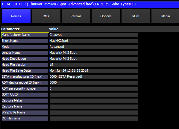
The Manufacturer Name, Short Name and Mode are used to identify the head to the system. These fields should be unique to the moving light. If you make a new head based on one of the standard ones then you should make sure you change the mode to a name of your choice.
The Short Name and Mode are used in display windows where there is not much space. You should ensure that these names are as short as possible and do not contain any spaces - preferably less than 8 characters.
The Longer Name is used as an alias to the Short Name - the Short Name will always be used in naming of personality files, but the Longer Name will be used to display the name in the Patch Window when choosing Head. The Longer Name should be exactly as the fixture is named on the web site of the manufacturer.
The Head Description contains details of the type of head – and is used for informational purposes.
The ESTA manufacturer ID, RDM device model ID and RDM personality number are used to match the head file to RDM-enabled fixtures. See the Remote Device Management chapter for more information.
The WYSIWYG and Capture patch information names indicate the names of this fixture in WYSIWYG and Capture to enable patch transfer from these visualisers.
Num Of Chans sets the number of channels for the head.
DMX Min, DMX Max and DMX Offset specify constraints on where the Head can be patched within the 512 DMX channels. Changing the Num of Chans will automatically change DMX Max.
Pan Range and Tilt Range are used in visualisation and by the FLIP function.
Pan Invert and Tilt Invert. These are used by the visualiser to specify which direction the yoke/beam moves.
Pan Speed, Tilt Speed
Zoom Narrow and Zoom Wide are used by the visualiser to specify the angle of the beam. For heads without a zoom set both Zoom Narrow and Zoom Wide to the angle of the beam.
Slowest Strobe, Fastest Strobe, Slowest Rot Speed, Fastest Rotate Speed are used by the visualiser.
Moving Head can be Mirror or Yoke - press ENTER to swap.
Colour Mix identifies the colour mixing channels – the options are:
CMY | For Heads with Cyan, Magenta and Yellow flags in front of a typically white source or incandescent lamp |
RGB | For Heads with Red, Green and Blue LED emitters |
RGBA | For Heads with Red, Green, Blue and Amber LED emitters, or Heads just with Amber emitter |
RGBW | For Heads with Red, Green, Blue and White LED emitters, or Heads just with White emitter |
RGBAW | For Heads with Red, Green, Blue, Amber and White LED emitters, or Heads just with Amber and White emitters |
RGBAWV | For Heads with Red, Green, Blue, Amber, White and UVLime emitters |
HSI | For Heads that are controlled using Hue, Saturation, Intensity channels. |
CIE XY | For Heads that are controlled using CIE XY channels |
The default configuration is CMY colour mixing – i.e. when the Cyan channel is at 100% and the Magenta and Yellow channels are at 0% you get Cyan. If your head uses RGB colour mixing – i.e. the above combination gives Red – then set the RGB option.
Virtual Chans. Some heads such as the Generic Scroller2chan are set up as a "Virtual" head – i.e. the channels in the head can be patched to any location on MagicQ – unlike normal heads where the channels are sequential from the DMX start address. In the View DMX view, the DMX address fields are used to specify the addresses for each channel in the virtual head – up to a maximum of 5 channels. (For normal heads these fields are used to specify multiple heads patched to one head.) Virtual heads could be used for other irregular fixtures such as water jet controls.
Virtual Dim. Used for heads with no Dimmer channel to force a virtual dimmer to be patched for each head.
Dimmer curve specifies the dimmer curve to be used for Intensity channels.
Framing type is used to specify the framing (shuttering) type.
MQTrack is specific to MagicQ tracking systems and is only used by MagicQ inbuilt head files.
Number of Emitters specifies the number of different colour LED emitters. When set to greater than zero, the emitter data is configured in VIEW EMITTERS.
The Multiple Heads Type and subsequent fields refer to Heads with multiple elements – see the section Heads With Multiple Elements below.
This view allows the different channels of the head to be specified. Note that once a head of the type has been patched it is not possible to change the number of channels of the head.
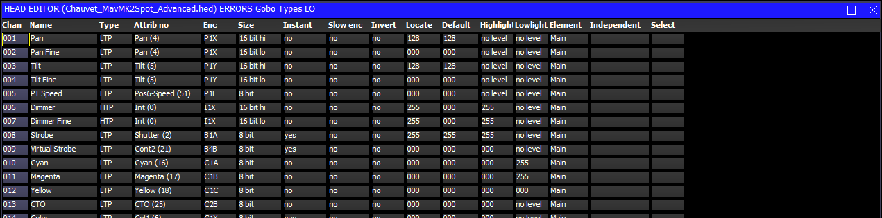
Channels can be added using the Insert soft button and deleted using the Remove Button (press twice to Remove).
The Name field is used to name the individual channel and distinguish it from other channels. If no name is specified then MagicQ will use the name of the attribute that it is assigned to.
The Type field is used to indicate whether the channel is Highest Takes Precedence (HTP) or Latest Takes Precedence (LTP). Generally only Intensity is set to HTP - all other channels are LTP. Note that if a head has combined Dimmer and Strobe channel then this should be set as Dimmer attribute with type of HTP.
The Attrib No field is used to identify the function of the channel to MagicQ. This is the most important field in the channel list - MagicQ uses it for determining how to control the Head, how to morph between different Heads, and to present information in the user interface.
Where a Head has more than one instance of an attribute, that attribute can be used multiple times with different Element numbers. An attribute of the same element number can not be used more than once except when specifying the high and low values of 16 bit or 24 bit attributes. See Element and Function Type below.
Table 27.1. Attrib No field
| Function | Attib No | Default Encoder |
|---|---|---|
Intensity | 0 | I1X |
Intensity Mode | 1 | I1Y |
Pan | 4 | P1X |
Tilt | 5 | P1Y |
Pos1 | 46 | P1A |
Pos2 | 47 | P1B |
Pos3 | 48 | P1C |
Pos4 | 49 | P1D |
Pos5 | 50 | P1E |
Pos Speed | 51 | P1F |
Col1 | 6 | C1X |
Col2 | 7 | C1Y |
Cyan/Red | 16 | C1A |
Magenta/Green | 17 | C1B |
Yellow/Blue | 18 | C1C |
White | 19 | C1D |
Amber | 27 | C1E |
Lime UV | 60 | C1F |
CTC | 24 | C2A |
CTO | 25 | C2B |
Col5 | 61 | C2C |
Col6 | 62 | C2D |
Col Speed | 26 | C2F |
Shutter | 2 | B1A |
Iris | 3 | B1B |
Focus | 12 | B1C |
Zoom | 13 | B1D |
Frost1 | 32 | B2A |
Frost2 | 33 | B2B |
Gobo1 | 8 | B1X |
Gobo2 | 9 | B1Y |
Gobo3 | 28 | B2X |
Gobo4 | 29 | B2Y |
Rotate1 | 10 | B1F |
Rotate2 | 11 | B1E |
Rotate3 | 30 | B2F |
Prism Rot | 31 | B2E |
FX1 Prism | 14 | B2C |
FX2 | 15 | B2D |
FX3 | 34 | B3C |
FX4 | 35 | B3D |
FX5 | 36 | B3X |
FX6 | 37 | B3Y |
FX7 | 38 | B3F |
FX8 | 39 | B3E |
Macro | 22 | B3A |
Macro2 | 33 | B3B |
Cont1 | 20 | B4A |
Cont2 | 21 | B4B |
Beam Speed | 40 | B4C |
Beam | Cont4 | 41 |
B4D | Cont5 | 42 |
B4X | Cont6 | 43 |
B4Y | Cont7 | 44 |
B4F | Cont8 | 45 |
B4E | Frame | 52 |
B5A | Frame | 53 |
B5B | Frame 3 | 54 |
B5C | Frame 4 | 55 |
B5D | Frame 5 | 56 |
B5E | Frame 6 | 57 |
B5F | Frame 7 | 58 |
B5Y | Frame 8 | 59 |
B5X | Reserved | 63 |
The Enc field specifies which encoder position in the Intensity, Colour, Position, Beam windows the attribute appears on. The Enc field is defaulted based on the choice of Attrib No - this provides a common interface across all heads. In some circumstances users may wish to modify the allocated encoder in order to bring similar attributes onto the same page.
On Compact console the encoders are positioned as follows:
Encoder A | Encoder E |
Encoder B | Encoder F |
Encoder C | Encoder Y |
Encoder D | Encoder X |
On stadium consoles. Encoder A to D are to the right of the main display and X, Y, E, F are horizontal above the programming buttons.
There is one page each for Intensity and Position, two pages for Colour and five pages for Beam.
The Size field is used to specify the size of the attribute. For channels that are only 8 bit the Size field is set to 8 Bit. For 16bit channels the coarse channel is set to 16 bit Hi and the fine channel to 16 bit Lo. For channels with 24 bit resolution set the lower two channels as for 16 bit and the highest channel to 24 Bit Hi.
The Instant field specifies whether a channel by default snaps immediately to new values rather than fading – this is useful for colour wheels and gobo wheels where you want immediate changes.
The Slow Encoder field makes the encoder works more slowly than normal. This is good for attributes where every possible DMX value represents a different function and therefore only very small turns of the encoder are required to change function.
The Default field defines what value the channel is set to by default on start-up. When the Setup, Programming option "Unused chans return to default" is set then channels also return to these values when they are no longer controlled by Playbacks or the Programmer.
The Locate field defines what value the channel is set to when a Locate is performed on the head – it is also used as the default value for a channel if no default values is specified.
The Default and Locate should specify the normal defaults for the head – the exact values used in a particular show can be overridden by making a Default Cue or Locate Cue in the Cue Store.
The Highlight and Lowlight values are used when the Setup, Programming option Highlight mode is set to Advanced. This enables the user to configure custom highlight/lowlight settings for each type of head.
The Highlight and Lowlight fields can be set to "No level" by pressing ENTER to determine which attributes are affected by the Highlight and Lowlight functions.
Note that setting the Highlight and Lowlight values for Intensity attributes to "No Level" may not have the desired effect. In Highlight/Lowlight mode, MagicQ will always try to perform a highlight/lowlight so that the heads in the current selection which are not sub selected appear differently to the sub selected heads. This ensures that a highlight/lowlight is performed correctly even if the personality has not been written correctly.
If you do not wish to have any lowlighting then in Setup, View Settings, Programmer set the Highlight Mode to "Advanced - highlight only (no lowlight)". In this mode only the sub selected heads will be highlighted. Heads that are selected but not sub selected will remain at their playback state.
The Element field is used for Duplicated personalities - these personalities have more than one instance of an attribute type within the personality - for example a LED moving yoke with three LED rings.
Heads are set as Duplicated Heads in the Multiple Heads Type field in the Head Editor. Duplicated elements always start from Element 1. All elements that are not duplicated are set to 0 (Main Element). For heads that have both a main element and a repeated element - e.g. a master RGB and then repeated RGB for each element then the master RGB is element 0 and the repeated RGBs start from 1.
For heads that have multiple functions, e.g. a central RGB beam and then a "eye candy" RGB element ring - the core RGB beam should start from Element 1, with the "eye candy" ring elements starting after the core RGB beam. Element 0 should only be used for Master channels, not for genuine individual control of elements - these should always be element 1 or higher. The Function Type field can be used to distinguish the different functions - i.e. Function 1 is the core beam, then Function 2 is the "eye candy" LED ring.
The Element field shows elements that are independent from Element 1 as Ind 2, Ind 3 etc…, whilst heads that are not marked as Independent are shown as Dup 2, Dup 3, etc…
Elements 2 and above of Duplicated Heads can be set as Independent.
When set to "Ind" all elements act independently and are made active in the programmer and programmed into Cues.
When set to "Dup" elements 2 and above are duplicated from element 1 when they are not explicitly in the programmer or active on a playback.
This field is hidden for element 0 and element 1 since they are automatically independent from each other.
When set to "Ind" then the "Select" field also becomes active and defaults to "yes".
Some heads have multiple elements that operate completely separately to each other - for example centre RGB cells, and then an outside eye candy RGB ring. For these heads it is possible to make it so that the additional, less important elements are not selected by default and therefore are only programmed when explicitly requested.
The Select field for channels for these additional elements should be set to "no". The channels will not be selected (and hence programmed) unless explicitly selected using the dot (.) syntax.
Note that this field only affects general selection of heads. Selection of specific elements, or selecting a Group with specific elements will cause the specified elements to be selected and this field to be ignored,
This field is used to distinguish between different element functions within the Head. When the Heads is patched if there is more than one function type in the personality MagicQ automatically generates separate groups for each function using the appropriate element mask. For example, if a Fixture has element 1 as core RGB beam, and elements 2 to 8 as "eye candy" ring - then set Element one to Function Type 1 and elements 2 to 8 to Function Type 2. MagicQ will then make a group with element 1 mask only for the Core Beam, and a separate Group with elements 2 to 7 mask for the "eye candy" LED ring.
This will also be used in strobes which have a Strobe function and a Plate function.
Each function must use different elements from the head - so if element 1 to 3 are used in Function 1, then elements 4 and above must be used for Function 2, and so on.
The function can be named in the function tab under VIEW OTHERS.
When functions are in use then all elements should be set to Independent. Duplicated elements are not supported when Function 2 and above are in use.
When all channels are set to use Function 1 then functions are not used.
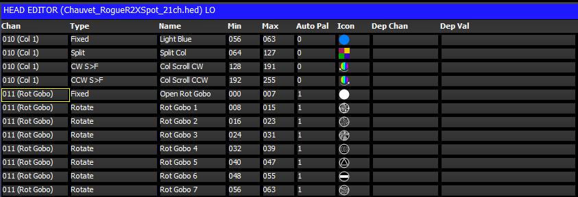
This view defines the ranges for channels that use specific values to access functions such as colour and gobo wheels, shutter channels and control channels. Ranges can be set up at any time regardless of whether heads of the type have been patched. The range data becomes immediately available. If the head has been patched then you can capture the minimum and maximum value fields from the programmer.
Ranges can be added using the Insert soft button and deleted using the Remove Button (press twice to Remove).
For each range you specify the channel number (starting at 1), the range type, the range name and the minimum and maximum DMX values for the range. The minimum and maximum values can be the same value if required.
The Range Type field is used to specify the function of this range so that MagicQ and MagicVis can recognise the features of the head. MagicQ automatically generates palettes for gobos, strobes, zoom, iris based on the range types. The range types are also used in visualisation.
The Auto Palette field was used to indicate Gobo channels for auto palettes prior to Range Types being added. This field can be used to force auto palettes for Gobo 1 or Gobo 2 that do not have a range type set to Fixed, Index or Rotate. Where Range Types are set this field can be set to 0.
Up to 20 Auto Palettes are supported per channel. Set this value to 1 for a specific channel function such as a Cone Gobo on a gobo wheel or a larger value for a graded parameter such as the rotate speed on a Gobo Rotate channel. The sum of all the Auto Palette fields for a particular channel should not exceed 20.
The Icon field is the icon displayed in the relevant Windows and soft buttons. Double click to select an icon from the large MagicQ icon library. The icons selected in the ranges are used by MagicVis for visualising gobos. For prisms select from icon category 50.
The Dep Chan and Dep Val fields enable ranges to depend on other ranges. This enables ranges to be defined for heads with attributes that change their function depending on the value of another attribute – such as FX parameters that depend on the particular FX chosen. The range is only valid when the dependent channel (Dep Chan) is set to the range specified in the dependent value (Dep val).
Ranges can be imported from a .csv format file using the Import Ranges
button. The data should be organised in the .csv file in the same column
order as the fields in MagicQ.
<chan>,<name>,<min>,<max>,<auto pal>,<icon>,<dep chan>,<dep val>
To capture the minimum and maximum values from the programmer you must first insert a new range and select the channel number you are interested in. Then using the Group, Position, Colour, Beam, windows in the usual way set the minimum value for the attribute. Back in the Ranges View, move the cursor to the minimum field and then press the Capture Range soft button. In a similar way, set up the maximum value in the programmer, move to the maximum field in the Ranges View, and then press the Capture Range soft button.
The "Attr test" mode enables the range to be tested on any patched heads of this type. In this mode moving up/down outputs the Range to all patched heads of this type. The value output is the middle point between the minimum and maximum – except when the cursor is placed in the minimum or maximum fields – in which case the actual minimum or maximum value is output.
This view defines the default palettes that are loaded when the head is patched. Palettes can be set up at any time regardless of whether heads of the type have been patched. The palette data is immediately available for patching new heads. When you have changed Palettes in the Head Editor you can regenerate palettes for heads that are already patched by using the "Regen Palettes" soft button.
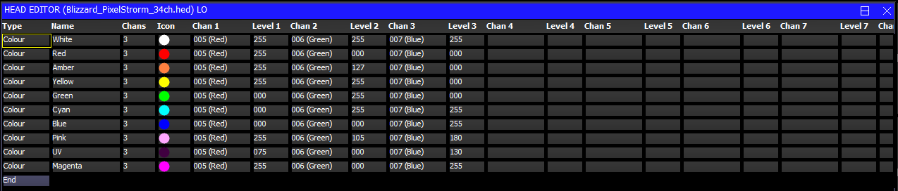
For each Palettes you specify the type (press Enter to swap between the types), the name and the number of channels that make up the Palette. Then for each channel you specify the channel number and the level for that channel.
Palettes can be added using the Insert soft button and deleted using the Remove Button (press twice to Remove).
The Icon field is the icon displayed in the relevant Windows and soft buttons.
Palettes can be imported from a .csv format file using the Import Ranges button. The data should be organised in the .csv file in the same column order as the fields in MagicQ.
<palette type>,<name>,<num of chans>,<icon>,<chan 1>,<val 1>,<chan 2>,<val2>,…
The icon field is normally a decimal number but MagicQ will accept icons numbers in hexadecimal if they have0h or 0x at the start of the number.
To capture the palette value fields from the programmer you must first insert a new palette and configure the channel numbers you are interested in. Then using the Group, Focus, Colour, Beam windows in the usual way set up the palette values. Back in the Palettes View press the Capture Palette soft button.
This view defines the macros that are available to control special features of the head such as turning the lamp on and off and resetting motor channels. Every head should have a macro named "Lamp On", "Reset" and "Lamp Off". MagicQ uses these macros in short cut keys for these functions.
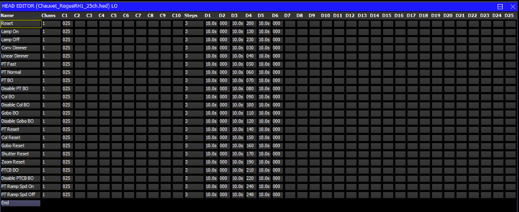
Each macro has a name and a number of channels. Up to 10 channels can be controlled by each macro.
The macro data consists of fields to specify which channels are used (C1 to C10) and then the macro step data. The macro step data consists of the number of steps followed by data fields.
The number of steps indicates how many steps are required in the macro – normally there are just two steps – the initial step to set the correct levels and hold them for a time (e.g. 5 seconds) and then a step that returns the channels to their default values.
The step data is specified in the fields D1…Dx. For each step there is a time for the step, followed by the values for each of the channels used for the step.
It is possible to load user icons from bitmap and jpeg files. In File Manager click on the .png or.bmp files you wish to make into icons. The icons will appear under the "User icons" icon class.
User icons are not stored in the show file, so when changing MagicQ systems it will be necessary to load the user icons onto each MagicQ console / MagicQ PC system.
MagicQ supports two methods for controlling heads with multiple elements - the original multi element heads which involved multiple personality files and the newer single personality file Duplicated elements.
In order to simplify the personality libraries, in early 2018 ChamSys converted all multi element heads to Duplicated elements. We recommend that all new personalities that have multiple elements use Duplicated elements.
In the Head Editor it is possible to convert between Multi elements and Duplicated elements.
For multi element heads, in Edit Head, View Chans press SHIFT and the soft button CONV TO DUP.
For duplicated heads, in Edit Head, View Chans press SHIFT and the soft button CONV TO MULTI.
Note that these conversion functions cannot be used if heads of the type are already patched in the show file - save as a different mode before attempting the conversion. If you then wish to convert patched heads then perform a morph operation.
The personality should be created in the same way as a personality with only single elements.
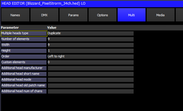
Then in the Head Editor, View General, Multi set the option "Multiple Heads Type" to "Duplicate".
Set the width and height appropriately ignoring the main element - so for example if an LED bar has a main element and 5 multi elements, set the Width to 5 and the Height to 1.
In Head Editor, View Chans set the element number for each channel. For attributes that are only used once in the head the element should be left at "Main". Attributes that are used more than once should be set to element 1,2,3 etc…
Elements 2 and above can also have the Independent and Select fields set.
For moving heads normally the Independent field should be set to "No" - this allows the head to operate with a single RGB control without having to program all the elements into all Cues.
For fixed LED bars the Independent field may be set to "Yes" - this means all the duplicated elements will operate independently.
For elements that should not be selected by default (e.g. eye candy LED rings) set Select field to "No".
From versions 1.6.6.2 MagicQ has improved support for Heads with more than one element of an attribute - for example a LED Wash light with 5 RGB elements or a club light with 2 tilt channels. Heads set as "Duplicated" now allow access to the individual elements and allow FX to be run over the individual elements.
By default the duplicated elements are treated as one element - so the 2nd, 3rd and 4th elements just copy the programming from the 1st element. This ensures that the Head is simple to use and appears to act as if it only had a single element.
When locating, selecting palettes and using soft buttons or encoders on attribute parameters only the first element is made active in the programmer and therefore only the first element is recorded into Cues. When the Cues are played back then MagicQ copies the calculated values from the 1st element to the other elements.
Individual elements can be selected using the dot (.) operator. For example to select the 1st element only, enter .1 NEXT HEAD or .1 @@. This sub selects only the 1st element. Pressing returns the selection to all elements. When a sub selection is active on a Duplicated Head then the specific elements will be made active in the Programmer and subsequently recorded into Cues. When the Cues are played back MagicQ uses the programming from the Cue for elements that have been recorded in to the Cue, only copying for elements that have not been recorded.
All elements can be selected if you wish to apply split times across all elements or to include all elements in a FX. Select all elements using the syntax .> @@
Palettes values are by default created for the first element. When a sub selection is in operation MagicQ will use the value in the Palette for the first element if there is no specific palette entry for the element selected - this avoids the need for creating separate palette information for each element. When a Palette is updated it will update Cues that use that Palette from the sub element if it exists in the Palette - otherwise it will use the data from the 1st element - ensuring that the Cue gets updated as expected.
When selecting FX for channels on a Duplicated Head that have multiple elements MagicQ prompts three options for applying the FX:
Dup Elements treats the elements as duplicated - i.e. all elements in the head do exactly the same thing. This is the default operation which treats all the elements in a head as one. In software prior to v1.6.5.8 this was the only supported mode of FX for Duplicated Heads.
Include Elements includes all the elements in the FX enabling separate control of each of the elements as if they were separate heads. For example if you apply a FX to 4 heads each with 3 elements then the FX would be spread over the 12 elements.
Use Elements runs the FX within the Heads, with all Heads performing the same FX synchronously across their elements. This is the same as Include Elements except that MagicQ automatically sets Parts to the number of elements within the heads causing all Heads to have the same offset.
Heads are set as Duplicated Heads in the Multiple Heads Type field in the Head Editor. In the Head Editor, View Chans the element field (cursor right) is used to indicate the different elements. Duplicated elements always start from Element 1. All elements that are not duplicated are set to 0 (Main Element). For heads that have both a main element and a repeated element - e.g. a master RGB and then repeated RGB for each element then the master RGB is element 0 and the repeated RGBs start from 1.
It is possible to specify a custom element layout for a Head, which is used when inserting multi element heads into Grids and for Group based Grids. This is particularly useful for heads with multiple elements arranged in clusters or circles - each of which has a completely different element ordering.
In View General, Multi, set the Order field to "Custom". This enables the "View Elements" view where it is possible to drag and drop elements into the pattern then best represents them on the grid. By default the elements are placed in a square - by pressing the "MOVE DRAG" soft button they can be easily dragged to the correct position.
Note that this grid organisation is designed for pixel mapping where heads fit onto a fixed grid - the "View Ele Data" has data fields for X,Y,Z position to enable more accurate real life element positioning - in the future this will be used in MagicVis and in Plot View.
To edit a head’s colourimetry data, it is first necessary to check that the head has the correct number of emitters defined. On the "Lamp" tab, find "Number of emitters"; this will be set automatically to the number of colour-mixing attribute types used, so confirm it is correct. For example, an RGB fixture has 3 emitters; a RGBAL has 5; and an RGBAWLV has 7.
Then, select the "Options" tab and press the "VIEW EMITTERS" soft button to show the emitters editor. Each emitter has the following parameters: - Attribute: this is the channel attribute associated with this emitter. This should be an attribute number in use by the fixture. - Name: a short name for the emitter; e.g. "Ultraviolet". - Chromacity X and Y; these are CIE 1931 colourimetry values for the emitter’s colour, from 0.0 to 1.0. - Luminosity: the emitter’s brightness. The preferred unit is lumens; however, for colour matching, only the relative brightness between the emitters matters. Therefore, you can also use luminance (lux), or a percentage.
These data can normally be found from a fixture’s manufacturer; however, it may not be specified by the manual, and some manufacturers may not measure their fixtures.
For more on colourimetry, see the Colour Picker chapter.
Older MagicQ supported multiple elements heads (e.g. RGB pixels), so that they can be patched in one action rather than patching the individual elements separately. When these heads were patched they continued to be controlled as separate heads.
Heads that consist of a single general element in addition to a repeated element are also supported. In these cases two different heads are required – one for the general element and one for the repeated element. The head for the general element is used for patching, and it references the repeated element to enable it to be patched automatically. It is possible to set the Multiple Heads Type field to specify whether the repeated elements are patched before or after the general element.
In the Patch Window, View Heads only the head general element is shown – however testing, moving, copying and setting the head no, affects all the elements in the head. The View Chans view continues to show the individual channels.
Heads with multiple elements can be inserted into the grid in one go. The Width, Height and Order fields in the head specify how the elements are arranged – for example the picture below shows Color Web 125 inserted into a grid. Color Web 125 has a strange DMX order with individual elements having a "L" shape rather than a square or rectangular shape.
It is possible to swap the repeated elements of a multiple element head around using the Swap field in the View Heads view. This is very useful, if for instance a LED batten has been rigged upside down.
When a head containing multiple elements is patched, a different head number will be allocated to each element. This enables each individual element to be controlled from the keypad and from the grid views. For heads that consist of a general element and repeated elements the general element will be allocated the base head number and the repeated elements will have increasing head numbers from the base element.
The Head Editor shows the full channel list in View Chans including the repeated channels.
MagicQ supports user custom gel libraries. User libraries are named usergels1.csv to usergels5.csv and must be stored in the show/heads/ folder. The files consist of parameters separated by commas.
<short name>,<long name>,<gel number>,<gel BGR value in hexadecimal>,<CIE X>,<CIE Y>,<transparency>
The gel number is a number between 1 and 999.
The CIE X, Y, and transparency are optional fields used for colour matching; if absent, they will be approximated from the hexadecimal colour. They range from 0.0 to 1.0. For more on colourimetry, see the Colour Picker chapter.
For example, Lee 106 is represented as
L106 Primary Red,Strong red effect cycloramas.,1106,3200F0,0.699,0.285,0.093
When MagicQ starts it loads the standard gel libraries and then looks for the five user gel libraries and if present loads them. Changes to the library files will not take place until restarted. The gel libraries are not stored in the show file so will need to be copied onto all MagicQ systems including remote PCs.
MagicQ supports the General Device Type Format (GDTF) for importing head files. To import a GDTF file, locate it in the file manager and select it by clicking or tapping.
If the GDTF file contains multiple modes, a dialog appears to ask which mode to import.
Import should finish within a few seconds. Once it is completed, a new head file will be saved into the heads directory; to distinguish it, the mode name of this file will begin with a "G-" prefix, for "GDTF". If problems are encountered when importing, a dialog will appear for a few seconds indicating that warnings were issued; see "GDTF Troubleshooting" below for details.
The software will switch directly to the patch window and the new head file will be selected as the fixture to patch. From here, press "PATCH IT" to patch the imported head, or "EDIT HEAD" to inspect the imported file.
Due to variance with the way that GDTF files are created, not all files may import correctly. MagicQ follows a "best-guess" approach when dealing with noncompliant GDTF files; this may lead to incorrect results in some cases.
If warnings are issued during import, it is advised to check the import log; this is located in the "MagicQ/log" directory, in a file called "gdtf.log". The most common types of warnings are the following: - GDTF attribute X is not recognised: this appears if unofficial GDTF attributes have been used. MagicQ will have attempted to guess how to handle channels with this attribute based on their names, which may fail. - ChannelFunction X has no ChannelSets: the GDTF file contains information about ranges, but the actual DMX ranges are not defined. A single range will be created which covers the entire DMX channel. - text "X" contradicts PhysicalFrom/PhysicalTo: the name of a range appears to contradict the direction that was encoded; "direction" here means "slow to fast", "wide to narrow", "high to low", etc. Check that range directions are correct. - Missing media files: the GDTF file references media files (likely for gobo images), but these were not found in the GDTF file. Gobo images will not be available.
If a GDTF file is severely malformed, the import process may abort with an error. This will appear on the MagicQ command line, and no head file will be created. If this occurs, contact the file creators to inform them of the problem.
| | ||