| |
| |
MagicQ supports a Network Manager (Setup, View DMX I/O, Net Manager) for monitoring and configuring network devices, including Art-Net and sACN nodes, RDM devices, GeNetix and SnakeSys products using the ChamNet protocol.

ChamNet devices include GeNetix Nodes (GW2I, GW2O, GN2, GN5 and GN10), legacy SnakeSys Nodes (B4, R4, R8 and T2 (T6), older ChamSys 5 port Ethernet Interfaces and 10Scene Gateways,
GeNetix Nodes can be configured in multiple different ways, via their front panel switches and buttons on the product (GN2, GN5 and GN10), via their inbuilt webserver or via Network using Net Manager window on MagicQ consoles. GeNetix nodes always operate in ChamNet mode.
When using a PC or Mac, ensure that the correct network host adaptor is chosen in Setup, View Settings, Network, IP address. If an invalid network host adaptor is selected then INVALID NET will show in the title bar and MagicQ may not be able to discover ChamNet devices.
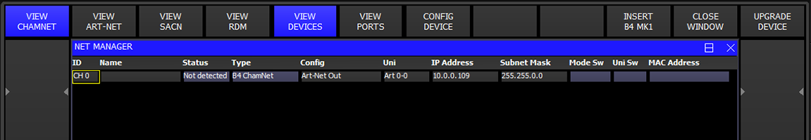
The ChamNet view has four tabs - Devices, Ports, Scenes and Options.
The IP address and subnet mask of the device can be set from this tab.
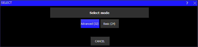
All GeNetix and SnakeSys nodes can be configured using the CONFIG DEVICE soft button and selecting an appropriate profile.
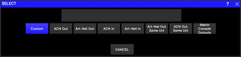
The profiles act as a starting point – once a starting profile has been chosen, the detailed configuration can all be set individually for each port by changing to the VIEW PORTS view.
At any time you can revert back to a standard profile by pressing the CONFIG DEVICE soft button – this will show the list of DMX profiles.
Identify mode can be turned on from soft button C.
When Identify mode is entered, all ChamNet devices are set to LEDs off except for one device which is set into Identify mode with all LEDs on. Stepping through the devices in MagicQ will Identify each device in turn.
When Identify mode is exited, all ChamNet devices return to their normal LED states.
GeNetix nodes with front panels indicate Identify mode on the display as well as turning on all the LEDs. SnakeSys nodes turn all LEDs on.
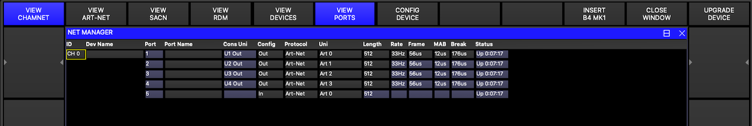
For GeNetix nodes ports can be configured as Disabled, Output, Input and Fallback. SnakeSys nodes do not support Fallback.
When configured as Outputs the ports can be configured to output the same or different Art-Net / sACN universes.
When configured as Inputs the ports should be configured to send different Art-Net / sACN universes.
The Cons Uni field shows the console universe on MagicQ that is outputting the data that the port is trying to read. If no console universe is set to output on that port then the field is blank.
The rate, frame, MAB and Break timing can be set for each interface – the timings affect all ports on the interface.
DMX Fallback enables fixtures on a single universe to be connected in a loop to two ports on the GeNetix node for redundancy. If a single cable is broken anywhere in the DMX loop, all fixtures can still receive DMX. Each port can be set to Output, Input or Fallback.
When a Port is set to Fallback it us by default operating as Input.
The node periodically checks for DMX being received in on the Fallback port – if after a timeout of at least 2 seconds there is no input detected then it changes into Output mode, outputting the Art-Net or sACN universe configured. When operating as an output, it periodically briefly changes to an input to sense whether DMX data is now being received – and if detected stays as an input. Periodic checking of the incoming DMX continues.
Different LED states are used to indicate Fallback configured, and in operation.
When using Fallback it is normal to set both the main output port and the fallback port to decode the same Art-Net / sACN universe.
DMX Fallback is supported within a GeNetix node and also between multiple GeNetix node. For example an installation could have a primary GN10 and a backup GN10 that provides both backup (in case node fails) and DMX Fallback (in case of cable failure/fixture failure).
The following LED colours are used:
Port set as Output
LED Colour | Description |
Dark Blue | Receiving good Art-Net/sACN data for this port (no Scene Active) |
Red | Receiving good Art-Net/sACN data for this port from 2 or more sources (no Scene Active) |
Cyan | Receiving good Art-Net/sACN data for this port (but Scene Active) |
Green | No Art-Net/sACN being received for this port (but Scene Active) |
Flashing Red | Test pattern being output |
Off | No Art-Net/sACN being received for this port |
Port set to Fallback
LED Colour | Description |
Yellow | DMX loop input being received |
Purple | No DMX input - fallback in operation |
Off | No Art-Net/sACN being received for this port |
Port set to Input
LED Colour | Description |
White | DMX input being received |
Off | No DMX input |
Note that during Identify all LEDs will be blue.
GeNetix nodes support storage of 10 Scenes that can be recorded from the incoming Art-Net or sACN data. Scenes contain DMX data for one or more ports on the node.
Recording of scenes can be initiated from the front panel or from MagicQ / QuickQ consoles.
Each Scene can have a name and a fade time.
Scenes can be replayed from the front panel or from the MagicQ / QuickQ Console. When a Scene is active the front panel display will show the Scene name and the DMX port LEDs will be Cyan or Green depending on whether incoming Art-Net / sACN data is still present.
Crossfading of scenes is performed on all channels – the use of fade times is therefore best when changing intensity and colours rather than on stepped attributes such as gobo wheels.
The complete set of Scenes can be managed from MagicQ, enabling easy control and modification of installations.
Scenes can be recorded on the GeNetix node by pressing the STORE SCENE soft button and selecting the Scene to store to from the choices in the dialog box. Alternatively press the RECORD button and select a Scene in the window. The GeNetix node stores the current state of its network data for all ports that are set as Outputs.
Scenes can be removed by SHIFT and the REMOVE SCENE soft button and selecting the Scene to remove. Only programmed Scenes will be shown in the dialog box. Alternatively press the REMOVE button and select a Scene in the window. The Scene is removed for all ports on the GeNetix node.
The Scenes can be retrieved from the node to MagicQ by pressing the RETRIEVE SCENES soft button and choosing the option of either the first 10 Playbacks or 10 items in an Execute Window. Playbacks and Execute Items will only be generated for the Scenes that are present on the node. If no Scenes are programmed then no Playbacks / Execute Items will be created.
MagicQ will only retrieve values for patched channels on the console universes corresponding to the ports on the GeNetix node. If MagicQ has no heads patched then MagicQ will patch generic dimmers on all the console universes corresponding to the ports on the GeNetix node prior to retrieving the Scene. This enables retrieving of Scene data even when the patch has been lost.
The Scenes can be sent back to the node from MagicQ by pressing the SEND SCENES soft button and choosing from Playbacks or Executes. If the Playback or Execute Item is not present then no Scene will be created. MagicQ will send value 0 for any channels that are not patched.
Scenes can be triggered from 10Scene Wall Plates when the 10Scene mode on the GeNetix is set to Scenes or Only Scenes.
When set to Only Scenes, then one of the Scenes is active at all times – this is useful for simple installations without consoles.
When set to Scenes, then Scenes are triggered from the 10Scene Wall Plate, but if all 10Scene buttons are off then no Scenes are active and the node operates normally passing through network data to DMX.
Set the IP address and subnet mask of the GeNetix node.
Note that in the GeNetix node must be on the same subnet as MagicQ in order to carry out firmware update and some other actions.
GeNetix nodes support synchronised DMX output to reduce tearing.
Synchronisation via ChamNet is available when used with MagicQ consoles.
Art-Net + sACN synchronisation is also supported.
The LEDs can be set to:
Normal = operate as normal |
Off - all controllable LEDs are turned off |
Locate - all controllable LEDs are turned on |
This forces a Scene from the GeNetix to be output on its DMX Output ports.
When set to "None" no Scene is output and the GeNetix node operates normally outputting the data it receives from the network.
The behaviour when a node loses network data (Art-Net or sACN) can be configured:
• Hold – holds the last output DMX values • Zeroes – outputs DMX 0s on all channels • None – stops outputting DMX • Scene – outputs the contents of the Scene. If the Scene is not programmed for one or more ports then those port hold the DMX
The network is only considered to be lost when data for all network ports configured as Outputs is lost.
GeNetix network nodes support ANSI E1.20 RDM which is enabled by default.
The GeNetix nodes only perform RDM operations when requested by the MagicQ or QuickQ console. They do not perform discovery on start up, or at predefined intervals – they only perform RDM discovery when explicitly requested by the console. This ensures that show critical DMX operation is not affected by RDM.
RDM on the node can be disabled on a menu option from the front panel and from the MagicQ console.
The node can also be set into a RDM Read Only mode. In this mode the GeNetix node will respond to RDM GET commands to receive information but will block all RDM SET commands. This enables users to discover the lighting rig, but not to change it.
All GeNetix nodes support saving and recalling of configuration data as User Configs.
User Configs can be saved and loaded from this option.
Configs can be triggered from 10Scene Wall Plates when the 10Scene Wall Plate mode is set to Configs.
GeNetix nodes support a lock PIN to prevent the configuration being modified from the front panel of the GeNetix and also optionally from all network interfaces. The PIN applies to each interface separately and each instance of MagicQ, QuickQ or web server.
When the lock PIN is active the PIN must be entered to use the menu system. The system can be relocked from the menu. When unlocked, after # seconds of inactivity the device automatically locks again.
When set to "All Interfaces" the PIN also restricts access from MagicQ and QuickQ consoles and from the web server.
Users that forget their passwords will need to contact ChamSys support to get a recovery code. Each device has a unique recovery code.
The GN5 and GN10 support timecode input and output.
Timecode can be input as LTC through the 3pin female XLR LTC In connector or via MIDI via the 5 pin DIN MIDI In connector. The GeNetix node can be configured to forward the timecode as Art-Net timecode, as ChamNet timecode for MagicQ/QuickQ and as GeNetix for other GeNetix nodes.
The GeNetix node can be set to broadcast the timecode or to send it to a specific IP address.
MagicQ consoles can be set to receive Art-Net or ChamNet timecode in Setup, View Settings, MIDI/timecode.
Timecode received on the LTC in or MIDI in port is automatically retransmitted on the LTC out and/or MIDI out ports depending on the Timecode Out setting.
The GeNetix node can receive Art-Net timecode from a MagicQ console or GeNetix timecode from another GeNetix node and output the timecode on the LTC out port and/or the MIDI out port.
To send timecode out of MagicQ set the Timecode Generation in Setup, View Settings, MIDI/Timecode to "LTC + Art-Net" or "MIDI + Art-Net". MagicQ will output timecode to Art-Net and any direct LTC or MIDI port.
The GN5 and GN10 support MIDI notes, MIDI change control, MIDI beat clock and MIDI system exclusive messages.
MIDI notes, beat clock and Sys Ex received on the 5 pin DIN MIDI In port can be forwarded over ChamNet to MagicQ and QuickQ consoles or over GeNetix to other GeNetix nodes. There is no support for sending MIDI messages to 3rd party consoles over network.
MIDI can be sent to a MagicQ or QuickQ console on a specific IP address via the MIDI In transmit host IP option. If it is set to 0, then the GeNetix broadcasts the MIDI messages.
MIDI notes, beat clock and Sys Ex received on the MIDI IN port are automatically forwarded out the MIDI out port as received.
MIDI notes, beat clock and Sys Ex received from a MagicQ or QuickQ console over ChamNet will be output from the MIDI Out port.
To send MIDI notes and Sys Ex out of MagicQ set the MIDI Out type in Setup, View Settings, MIDI/Timecode to "ChamNet Any Chan" or "ChamNet Req Chan". MagicQ then outputs any MIDI notes and Sys Ex messages from the Cue Stack N Macro to ChamNet and any direct MIDI out port.
The GN5 and GN10 have a 10Scene port. This can be configured to be used in different ways:
• None • Scenes (Default) • Only Scenes • User Configs • Gateway
When set to Scenes it control the Scenes within the GeNetix node. When no 10Scene buttons are active then no Scenes are active and the GeNetix node operates normally with DMX control from a console.
When set to Only Scenes then one Scene must always be active and DMX control from a console is not supported. This is designed for installs where there is no console.
When set to User Configs, pressing the 10Scene button loads the User Config.
When set to Gateway the 10Scene functions like it is 10Scene Gateway. From MagicQ/QuickQ it is interchangeable with a 10Scene Gateway.
SnakeSys Nodes can be configured in two different ways – in normal mode the product is configured from the front panel switches and buttons on the product. In ChamNet mode the switches and buttons are ignored and the product is configured from MagicQ only.
If the SnakeSys product is set in a mode other than ChamNet Mode (such as Art-Net, ACN or buffer) then it is not possible to configure the interface from Net Manager. However, the device will still appear in Net Manager and it is possible to view its configuration.
In ChamNet mode each SnakeSys product on the network has a different ID in the range 0 to 99. All interfaces should have different IDs.
The ID is set on the SnakeSys product using either the control panel or rotary switches. The 10Scene Gateway ID can only be configured through Net Manager as it has no physical buttons on the device.
Older ChamSys 4 Port Ethernet Interfaces and the SnakeSys B4 interfaces manufactured prior to 2013 (serial numbers with last 4 digits less than 0268) have no storage for configuration data and so when in ChamNet mode they always get their configuration from MagicQ every time they are powered up.
When the interface starts up it will recognise that it is in MQ Mode and then will search on the network to find a MagicQ system that can give it a configuration. The interface will not output or input DMX data until it has received configuration from a MagicQ system.
The MagicQ system stores the configuration information for all these older interfaces as console settings. In View Ports, press the INSERT B4MK1 button to add a new interface. MagicQ will present a list of default profiles for configuring the interface.
An interface can be removed by putting the cursor on the line of the interface and pressing REMOVE.
If there are multiple MagicQ consoles on the network, then only the master one (as per Hot Takeover) will provide configuration information to the interfaces.
Newer SnakeSys B4s and all other SnakeSys and all GeNetix products will appear automatically in the list and do not need to be inserted or removed.
GeNetix and SnakeSys nodes can be firmware upgraded from MagicQ software - the latest MagicQ software contains the latest firmware for all GeNetix and SnakeSys products - this can be found in the firmware folder under on the installation.
ChamSys recommend not attempting a firmware update in a critical show environment.
Download the latest MagicQ software from the ChamSys download site. In order to upgrade GeNetix devices, MagicQ must be running software version 1.9.5.0 or above.
If you are sent a newer firmware file by ChamSys support then copy the file into the firmware folder in the MagicQ installation. To install it onto a MagicQ console put the file onto a USB stick, then in MagicQ go to Setup, File Manager. Select USB DRIVE. Press COPY and select the file as the source to copy. Then select the destination, by selecting HARD DRIVE, UP DIR, and select the firmware folder. Press the "." item to copy to. Then follow the procedure above.
The firmware has the filename firmware_XXXX_YYYY or firmware_XXXX_XXXX_YYYY where the XXXX or XXXX_XXXX is the product code and YYYY is the firmware version number. The product codes are:
GeNetix nodes start up in a boot firmware, indicated red on the front panel display before starting the main application firmware. During firmware upgrade the nodes return to boot code. If for any reason the main application fails to program or run then the GeNetix node will return to the boot firmware and can be upgraded again.
In order to use a GeNetix or SnakeSys node with a MagicQ system the MagicQ system must be set up in Setup, View DMX I/O to output or input universes over the network
When outputting from the GeNetix node set up MagicQ universes with Output type of Art-Net or sACN with the Out Uni set to the Art-Net or sACN universes that the GeNetix node is set to decode.
For inputting DMX from the GeNetix node set up MagicQ universes with Input type of Art-Net or sACN with the In Uni set to the Art-Net or sACN universes that the GeNetix node is set to generate.
This view shows all Art-Net devices detected on the network. This includes all MagicQ consoles, QuickQ consoles and stand alone MagicVis and MagicHD applications as they all have Art-Net capability.
Press REFRESH NODES to force MagicQ to clear its table of Art-Net nodes and re-detect all nodes.
For each node that it detects it shows the IP address, node name and port configuration.
For each port it shows the universe that the node is set to output or input. The universe is preceded by the following letters to indicate status:
For Art-Net ports the universe is the Art-Net universe (starting at 0) for sACN it is the sACN universe.
Note that whether these indicators are displayed is entirely dependent on the node and whether the manufacturer has implemented these fields in their Art-Net implementation. Where the node supports it, it is possible to directly configure the ports of the node by setting the Universe value in the Port Field.
GeNetix nodes fully support configuration over Art-Net.
Type S or s in the Port field to set the port to sACN. Type A or a in the port field to set the port to Art-Net.
Type I or i in the Port field to set the port to Input. Type O or o in the port field to set the port to Output.
Press RDM DISCOVERY to force an Art-Net node that supports RDMM to perform discovery and retrieve the RDM table of devices. Any devices that are detected will be shown in the VIEW RDM menu. SHIFT + GET RDM TOD retrieves the table of devices (TOD) without forcing the node to do a discovery of new devices.
Press VIEW STATUS to jump to the Output Window, Art-Net View to see the number of Art-Net packets being received on Art-Net universe 0 to 255.
This view shows all sACN RDMNET devices detected on the network. In order to detect RDMNET devices the IP Address and port of the RDMNET gateway must be first configured in Setup, View Settings, Network.
Once a RDMNET gateway has been detected, use GET ENDPOINTS to get the Endpoint data.
This view shows RDM devices.
MagicQ stores the list of RDM devices (to enable restoring of a lighting rig via RDM) in the show file, so the device list may contain devices that are not currently accessible.
Devices that have been discovered in the current session are shown in white, whilst devices that have been discovered in previous sessions and stored in the show file are shown in grey.
Press SHIFT and CLEAR RDM to clear all stored RDM devices out of the MagicQ show. Alternatively, use REMOVE to remove one or more individual entries.
Press DISCOVER ALL to discover RDM devices. MagicQ will attempt to discover RDM compliant devices on its direct console ports (MQ50, MQ70, MQ80, MQ250M and Stadium Connect) and via connected Art-Net nodes that support RDM.
When MagicQ detects the RDM devices it will automatically attempt to get information from each fixture in turn on all. Some devices may not respond immediately - in this case it may be necessary to press GET INFO to force this information to be retrieved.
If the RDM devices are connected to an Art-Net node and nothing is detected then check that your RDM-enabled Art-Net node appears in VIEW ART-NET.
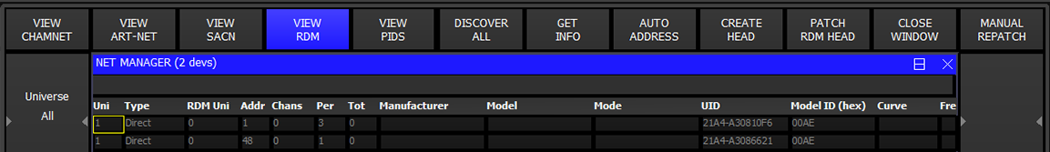
The fixture address, mode, dimmer curve and modulation frequency can be set directly for each RDM device shown in the Window. It is also possible to factory reset devices that support it.
Columns
To further configure the manufacturer parameter PIDs of each connected RDM device, put the cursor on the required device and press VIEW PIDS.
Note that The DISCOVER ALL command requests Art-Net nodes to perform a flush of their RDM table of devices (TOD) and to then perform a discovery of all currently connected devices. In some cases it may be useful to just retrieve the table off devices without forcing a new discovery - in this case press SHIFT + GET TOD ALL. .
Press the AUTO ADDRESS soft button to automatically address all the fixtures in the list, starting at 1 and incrementing based on the channel count of each fixture.
Where there are devices from more than one universe the devices on each universe will be addressed starting at 1.
Once a DISCOVER ALL and GET INFO has been performed on a lighting rig, MagicQ stores the RDM address and mode for each fixture with its unique UUID in the show file. This is maintained in the show file through subsequent loads and saves of that show file.
At any time a lighting rig can be restored to a known state from a MagicQ show file.
First in Net Manager perform a DISCOVER ALL and GET INFO to get the addresses and mode of the RDM devices. Check that all the expected devices have been detected.
Then press SHIFT + RESTORE ADDRESS and select a show file to load the RDM information from. MagicQ loads the RDM data from that show file and readdresses the RDM fixtures to the mode and address from that show file. Note that MagicQ only loads the RDM information from that show file, it does not load or change any other data in your show.
When setting up a new venue, or a new lighting rig that uses RDM when the configuration is complete it is recommended to DISCOVER ALL and GET INFO for the complete rig and save the MagicQ show file with a name such as "VenueRDM.shw" which can then be used in the future to restore the lighitn rig to the correct RDM state.
The RDM identify command forces a fixture to identify itself. This is usually a flashing white light or continuous pan, tilt and colour scroll. This allows you to match up the devices you are seeing in the VIEW RDM window with physical devices on the lighting rig, similar to the Head Test feature in the Patch window.
In the VIEW RDM window, press soft button C, RDM Test, and use the cursor keys to scroll up and down the list of devices. The device at the cursor will be sent the RDM identify message and highlighted red to show it is in test mode.
Sensor information for the RDM device at the cursor is displayed at the top of the window and is continually refreshed. If the device is able to report multiple sensors then they are all shown.
Pressing the PATCH RDM HEAD soft button will patch the RDM device at the cursor into the show, using its current DMX address and mode.
Press SHIFT and PATCH ALL RDM soft button to patch everything in the list.
This tries to find a matching head file using the ESTA Manufacturer ID, Device Model ID and mode. If this fails it tries to match the manufacturer and model descriptions and channel count.
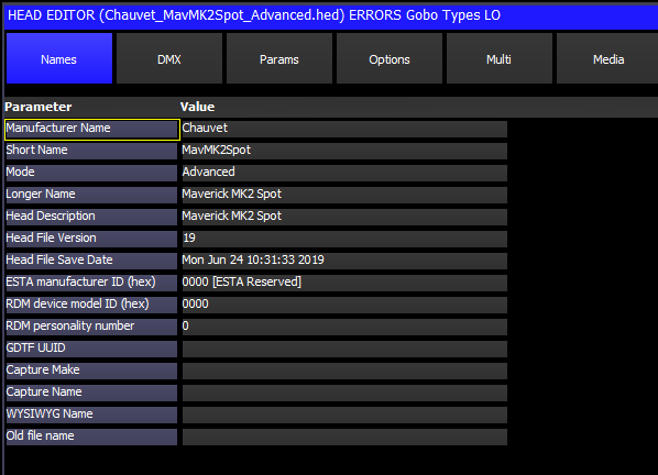
To improve the accuracy of the auto patching feature, you can add in the RDM information into the head file using the head editor. In the General View there is
The ESTA Manufacturer ID, Device Model ID and Personality number are all reported by the fixture over RDM and together can be used to match a specific head file. You should not have more than one head file with all three of these fields the same.
MagicQ has an extensive personality library which covers nearly all fixtures. MagicQ personality library has very detailed modelling of fixtures including gobo icons and physical dimensions.
RDM optionally allows fixtures to provide basic reporting of attribute allocation enabling MagicQ to create a basic new personality which can be then used to patch the head.
Put the cursor on the required device and press CREATE HEAD to create a new personality. The name of the personality will be based on the Manufacturer, Model and Mode fields reported by the RDM device.
Note that creating heads is only possible if the RDM device supports the RDM SLOT_INFO PID.
MagicQ provides shortcuts for repatching a lighting rig RDM compliant fixtures in it.
There are two options - Readdress physical fixtures and Repatch show to fixtures.
This is used when you want to change the addresses on the physical fixtures in the venue to match your show file - for example, when setting up a lighting rig for the first time where the fixtures have not yet been addressed.
Readdressing physical fixtures does not change the Patch information or any of your programming in your show - instead it uses RDM commands to change the address and mode of the physical fixtures, just as if you were changing them on the fixture control panel.
First press DISCOVER ALL and GET INFO to get the RDM information for the RDM compliant fixtures in the lighting rig.
Then press MANUAL REPATCH and select Readdress physical fixtures. "RDM Readdr" will flash in the status window under the clock whilst RDM Readdr mode is in operation.
In RDM Readdr mode the fixture at the cursor in Net Manager is automatically tested (identified) to identify the fixture in the physical lighting rig.
Use the NEXT HEAD and PREV HEAD buttons to move to different fixtures in the lighting rig. Note that the NEXT HEAD and PREV HEAD buttons are not used to select heads whilst in RDM Readdr mode.
To readdress a RDM fixture to match a head in your show use one of the normal MagicQ head selection operations - either:
The RDM device will be readdressed and set to the mode of the selected head in the MagicQ show.
Use NEXT HEAD or PREV HEAD to change to another RDM fixture, and then select the head in the MagicQ show to readdress this fixture to.
When all readdressing has been done press the END READDRESS button in the Net Manager.
This is used when you want to change your show data to match the DMX addresses and modes of the physical fixtures in the venue - for example, when touring and visiting a venue with a fixed lighting rig.
Repatch show to fixtures does not change the address, mode or any other parameters of the physical fixtures - instead it morphs your show file to the physical fixtures and repatches the addresses to match the physical rig.
First press DISCOVER ALL and GET INFO to get the RDM information for the RDM compliant fixtures in the lighting rig.
Then press MANUAL REPATCH and select Repatch show to fixtures. "RDM Repatch" will flash in the status window under the clock whilst RDM Repatch mode is in operation.
In RDM Repatch mode the fixture at the cursor in Net Manager is automatically tested (identified) to identify the fixture in the physical lighting rig.
Use the NEXT HEAD and PREV HEAD buttons to move to different fixtures in the lighting rig. Note that the NEXT HEAD and PREV HEAD buttons are not used to select heads whilst in RDM Repatch mode.
To repatch a head in your show to use the physical fixture select that head using one of the normal MagicQ head selection operations - either:
The head in the MagicQ Patch will be morphed to the RDM fixture, and it will be moved to the DMX address that the RDM device reported.
Use NEXT HEAD or PREV HEAD to change to another RDM fixture, and then select the head in the MagicQ show to repatch for this fixture.
When all repatching has been done press the END REPATCH button in the Net Manager.
Use soft button F to enable background RDM checking. When Background Check is on, MagicQ performs a RDM discovery every 60 seconds to detect RDM devices and get their info.
When Background Check is off, MagicQ only performs RDM discovery when requested by pressing the DISCOVER ALL button.
Note that Background RDM checking requires a lot of RDM traffic, particularly on larger lighting rigs or with complex fixtures, which may slow down DMX refresh rates.
Auto Patch enables a lighting rig to be detected and patched automatically. It also enables the show to be updated if any devices have had their address or mode changed.
Use soft button Y to enable RDM auto patching. When Auto Patch is on, then Background Check is automatically turned on.
When Auto Patch is on, MagicQ performs a background discovery and patches any new devices that it had not previously encountered in the show using the current device mode . If MagicQ determines that devices that it had previously auto patched have changed DMX address or mode then MagicQ will change the DMX address or mode of the patched Head in the show.
Note that MagicQ does not remove Heads from the Patch if devices are not detected - this ensures that the show programming is maintained. If devices are permanently removed from the lighting rig then they must be manually unpatched from the show.
Rig Lock enables a lighting rig to be locked so that users cannot change the DMX address or modes of fixtures.
Use soft button X to enable RDM Rig Lock. When Rig Lock is on, then Background Check is automatically turned on.
When Rig Lock is on, MagicQ performes a background discovery and checks any devices found. If the device address or mode has been changed then MagicQ sends a RDM command to return the device to the address and mode from its show file.
Rig Lock takes priority over Auto Patch. Generally Auto Patch should be set to off when Rig Lock is in use.
RDM fixtures support parameters referred to as PIDs. Parameters can be "Get" - i.e read only, "Set", i.e. set only, or "Get and Set".
All RDM fixtures must support the parameters used for discovering the device, identifying the device and setting the DMX start address.
In the VIEW PIDS all the PIDs that the device reports that it supports are shown. For each parameter there is an ID (as defined by the RDM specification), a description and the current value.
Standard PIDs have IDs in the range 0x0001 to 0x7FFF. Manufacturer specific PIDs are in the range 0x8000 to 0xFFDF.
The Size, Data Type, Min, Max, Type, Default, Unit and Prefix fields give more information about the particular parameter.
For parameters that are "Set" or "Get and Set" the Value field can be set. Enter a new value on the keyboard to change the value.
Press REFRESH PIDS to reload the PIDs from the device.
The GET SLOTS and LOG RDM soft buttons are used for testing RDM fixtures. Press GET SLOTS to force MagicQ to get the DMX Slot information (fixture attribute information) from the RDM device. LOG RDM writes all the details that have been retrieved from the RDM device including the general info, modes, slot info and PIDs to the file "rdm.csv" in the log folder.
Press COPY PID to copy the PID that the cursor is on to all devices of the same type. Press SHIFT + COPY ALL PIDs to copy all PIDs to all devices of the same type.
MagicQ supports remote control and monitoring of up to 10 separate Lyntec relay or motorised break control devices.
MagicQ supports individual zone control on the 12 Lyntec zones, or individual circuit control on up to 168 breakers / relays per Lyntec device.
In Net Manger the VIEW LYNTEC enables configuration of connections to Lyntec devices and monitoring and changing of status of Zones on the Lyntec devices.
Connection to each Lyntec device is via TCP/IP. MagicQ stores an IP address, user name and password to connect to for up to 10 Lyntec devices.
When connected, the Zone information shows the Zone name and status for each Zone. The status is On, Off or Processing. Pressing ENTER when the status in On changes the status to Off. Pressing ENTER when the status is Off changes the status to On.
In Net Manger the VIEW LYNTEC CHANS enables monitoring and changing of individual breaker or relay channels on the Lyntec devices.
When connected, the channel name and status is shown for each channel. The status is On, Off, Tripped, Faulty or Empty. Pressing ENTER when the status in On changes the status to Off. Pressing ENTER for status of Off or Tripped status will attempt to change the status to On.
Lyntec devices can be controlled automatically from MagicQ uses Automs in the Automation window and Cue Stack Macros.
| | ||