| |
| |
MagicQ utilises a powerful Cue engine, which enables it to easily handle large numbers of LED heads in the form of panels, battens and moving lights. MagicQ’s ability to handle large numbers of heads independently ensures that Lighting Designers get to make the most of their LED arrays without being limited by the console. With MagicQ you can generate complete rainbow washes across all LED heads at the touch of a button with immediate live control during playback through encoders and buttons.
MagicQ includes a powerful Pixel Mapper designed for use with arrays of LED heads. You can design a grid structure based on the layout of the heads on the stage and then play back movies, bitmaps and text messages on that grid. The grid can have spaces in it allowing the heads to be spread over the grid as they appear on the stage.
![]()
MagicQ enables LED heads to be used in their "high resolution" mode enabling individual control of each LED pixel rather than the restricted modes where Lighting Designers are reliant on the same old in built effects that everyone has seen many times.
![]()
![]()
We recommend that you patch LED heads in their highest resolution mode (maximum number of controllable RGB elements) and chose a mode without extra inbuilt FX channels if possible.
The generic led3chan and generic led4chan can be used with most LED heads. If MagicQ does not have the required personality in its library then you can easily build your own personality using the in-built Head Editor.
For LED heads without dimmers we recommend you patch the RGB channels as HTP. For LED heads with an inbuilt dimmer channel the RGB channels should be LTP.
After patching your LED heads you should set up the head numbers for each head in the Patch Window. By default MagicQ numbers heads in the order they are patched starting at 0. Simply edit the head number field in the Patch Window to change the head numbers. Use SHIFT and the cursors keys to set multiple head numbers.
To make the most of your LED head you can create a grid containing the LED head and then each head becomes a "pixel" in the grid. The MagicQ Pixel Mapper can then be used to play back movies, bitmaps, text and FX on the grid.
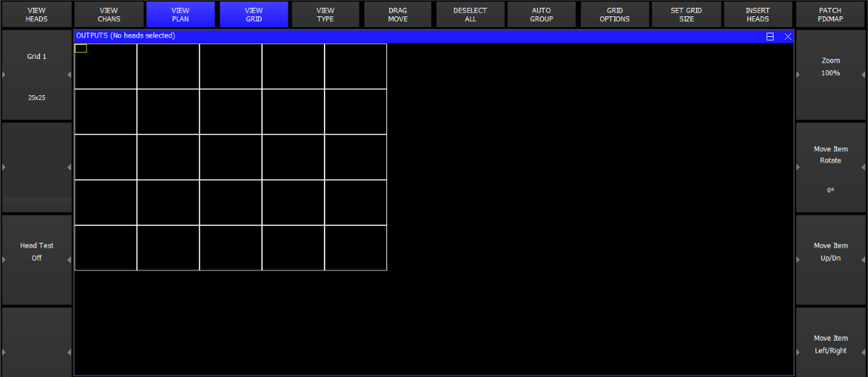
In the example above, we patched a 20 by 20 matrix of RGB pixels (total 400 pixels) on Universes 4.5 and 6.
In the Outputs Window select View Plan.
The View Grid soft button is used to show and edit the grid.
The data shown in each grid cell can be changed by pressing View Type. Choose between Head Names, Head Nos, Head Nos + Int, Cols and Cues. When Cues is selected the grid shows data from the currently selected playback rather than from the Output.
Set up the grid size, by pressing the GRID SIZE soft button. Enter the horizontal size followed by the vertical size separated by a forward slash – e.g. 20/20.
Use Encoder E to zoom the grid.
You can enter the head numbers in the grid according to the layout of the LED heads within the matrix / stage. Put the cursor on the desired item and enter a head number on the keypad. To insert multiple head numbers in one go use SHIFT or CTRL and the cursor keys to set multiple head numbers in one go before entering the starting head number.
To set multiple items in a particular orientation then put the cursor on the starting item then move in the direction you wish them to number - for example to number from bottom right to top left going horizontally first, then put the cursor on the bottom right, press SHIFT and move left to the left corner and then up to the top left corner.
Note that it is not necessary to allocate a head number to every position in the grid – so if your LED heads are placed at weird angles you can make a grid with the LED placed as you would see it. Multiple grids can contain the same head numbers – so it is possible to have one grid with the LED tightly packed and anther representing how they are really spaced out.
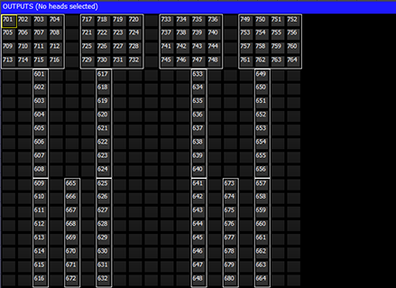
To insert the currently selected heads into the grid use the INSERT HEADS soft button. If no heads are currently selected then all patched heads will be inserted.
The Insert Heads soft button has 5 options - Horiz, Vert, 3D, Dup Ele and Col Web.
Horiz, Vert insert into the Grid in the horizontal or vertical direction. Multi element heads will be inserted into separate grid cells according to the width and height specifiers in the personality. Duplicate element heads will be inserted as a single cell.
3D is used for inserting for 3D pixel mapping in the 3rd dimension - only multi element heads can be inserted in 3D.
Dup Ele is to insert all the elements of a Duplicated Element head into the grid as separate cells.
Col Web is for inserted Col Web only.
From 1.7.6.4 the Output, View Grid view shows spare heads that have not yet been inserted in the grid in a space below the grid.
For group based grids the spare heads will include any heads from the Grid group that have not been inserted in the grid.
For normal grids it shows any currently selected heads that have not been inserted into the grid. This enables easy inserting of heads into a grid - first select the group in the Group Window and then they will appear below the grid in the Grid View.
For grids that are set to Grid Type = Groups, then the space below the grid will show any programmed groups from the Group Window that have not been inserted into the grid.
Move heads into the grid by moving in the normal way (press MOVE, source, destination). Alternatively press the DRAG MOVE soft button to drag and drop.
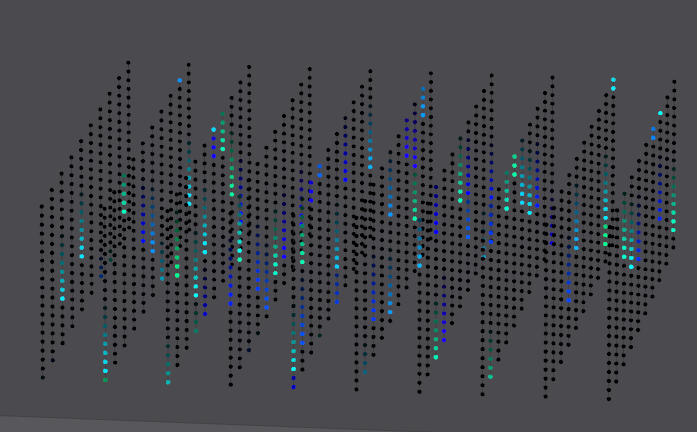
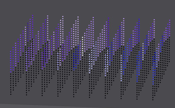
Once the grid is configured you can then see the Output by pressing the View Colours soft button and the View Grid soft button. For instance, below you can see the Output when all 400 heads were selected from the Group window (using the All LED3chan group) and then a RGB FX was played back on them.
You can test the head selected in the grid using the test mode to the Grid selected via soft button C. In test mode the head under the cursor is tested (located). This enables the grid layout to be easily checked.
MagicQ software contains an in-built Pixel Mapper that appears as a media server just like an external media server. The Pixel Mapper can be used to play back images, movies, text and FX on a grid of LED, dimmers or moving lights.
If the heads in the grid have colour mixing then the pixel mapping will operate on the RGB (or CMY). If they have no colour mix then the pixel mapping will operate on the Colour Wheel or if there is no colour wheel, then on the intensity. The pixel mapping can be set to always operate on the intensity regardless of head type.
When the Pixel Mapper is patched for a grid then MagicQ sets up the media settings automatically so that the Pixel Mapper appears in the Media Window.
Once a grid has been designed in the Plan View of the Outputs Window, then pressing the PATCH PIXMAP soft button automatically patches the internal pixel mapper (personality generic bitmapfx2).
![]()
MagicQ asks the user to specify the number of layers required and will patch that number of layers (generic bitmapfx2 heads). The layers will be named according to the grid that is selected in the Outputs Window. MagicQ uses head numbers above the other patched heads.
When operating on a layer within the pixel mapper it will default to operating on the grid that was selected when it was patched. MagicQ overrides the default value for Grid Number specified in the Head Editor for generic bitmapfx2.
MagicQ automatically adds the settings for the Pixel Mapper to the Media View of the Setup Window. This enables the Pixel Mapper to be accessed immediately from the Media Window without further set up.
MagicQ supports a total of 20 pixel map layers per show. This could be a single pixel map of 20 layers, or any mix of multiple pixel maps. For example 5 seperate pixel maps all with 4 layers each.
The bitmaps and text are controlled using bitmap layers – each layer is controlled like a normal moving light – i.e. it is patched as a virtual personality - generic bitmapfx2.hed. The personality has channels to select the bitmap or text, channels for X, Y position and size, rotate and master levels for red, green and blue. Multiple layers can be used to mix between the layers using add, subtract, min, max or invert colour mix modes.
Each bitmap layer uses 40 channels from the output channels. When you patch the Pixel Mapper from the Grid View, MagicQ chooses free channels for the layers. These channels are then reserved for the pixel mapper layers and can not be used for controlling real lights. It is best to patch generic bitmap layers to unused universes or to set them as unpatched.
The Bitmapfx2 is patched to the encoders as follows
FX, Text and Media interact according to the following priorities, with FX having the highest priority and Media the lowest.
FX Page If FX Type is greater than 0 then FX has highest Priority
Text Page If Text 1 is greater than 0 or Text 2 is greater than 0 then Text has priority over media
Media Page Media has the lowest priority
In the Media Window the Media Page (encoder Y) is used to select the media that is played on the grid. The Media pages are as follows
The Pixel Mapper contains a library of standard bitmap patterns on Bitmap Page 0. These patterns are automatically sized to the size of your grid.
Select the Pixel Mapper, Layer 1 and press LOCATE to set the layer to its defaults.
![]()
After a Locate the Media parameters will default to the white cross. Use the touch screen or encoders to select different Bitmaps.
MagicQ supports custom image files in .bmp, .jpg or .png format. These can be loaded using the LOAD PICTURE soft button in the Media window.
Alternatively, images can be manually copied into the Pics 1-4 pages by copying the images into the bitmaps folder within the show folder. The images should be named with the format bitmap001-001.bmp. The first 3 digits are the bitmap page and the second 3 digits the bitmap within the page. bitmap003-025.png would appear on page 3, in the 25th slot.
Bitmap page 0 is reserved for standard, internally generated bitmap patterns.
It is best to make user bitmaps the same size as the output grid. By default User bitmaps and icons from the internal library are applied to the grid using their normal size. It is possible to make MagicQ scale the user bitmaps and internal icons to the size of the grid - use the Apply Type "Scale to Grid" to resize a bitmap to the full grid size.
Media pages 128 to 255 select the icons from the gobo / colour library. The icons are all based on 32 by 32 pixels – but they can be sized in the Position Window to fill the required grid size.
MagicQ supports playback of movies as well as bitmaps. MagicQ supports up to 1024 different movie files.
Movies are accessed through the Media Page – there are 4 ranges on the "Media Page" encoder – Movie 1, Movie 2, Movie 3, Movie 4. These ranges are after the Inbuilt Page and Pics Pages.
User pictures and movies can be loaded into the internal pixel mapper directly from the Media Window using the LOAD PIC / LOAD MOVIE soft button available when the Pixel Mapper server is selected.
Movies are stored in the movies folder (show\movies) in a similar way that bitmaps are stored in the bitmaps folders. Movie files are stored in a special ChamSys movie format which compresses the data to the required grid resolution. The files are named movie001-001.cmv, movie001-002.cmv, etc…
ChamSys movie files can be created in MagicQ on PC/Mac using Tools, CMV Converter.
When converting movie files we recommend you choose the same movie resolution as your grid size on MagicQ. Click the auto install feature to automatically install the converted media file into the movies folder naming it with the next free movie ID.
The speed of movie playback can be controlled by the movie speed encoder.
When converting media, by default, the media file will play back at the MagicQ lighting rate of 33.3fps irrespective of source frame rate. So, for example, if your movie has a higher frame rate than 33.3 the playback of the converted file is slower than the original.
If you use the "Preserve media duration" option it will convert your media file to 33.3fps to match MagicQ’s lighting engine and thus play back the movie at its native source frame rate.
From v1.9.1.4 support for playing movie files has been improved with the implemention of the Movie Mode attribute. Previously this was marked as Movie Direction but was never implemented. The new modes are:
Whole movie | 0 | Plays movie from start to finish looping, restarts when Movie is changed |
Frms | 1 | Plays clip from start to end point (in frames) looping, restarts when Movie is changed |
Secs | 2 | Plays clip from start to end point (in secs) looping, restarts when Movie is changed |
Whole, Once | 8 | Plays movie from start to finish looping, restarts when Movie is changed |
Frms, Once | 9 | Plays clip from start to end point (in frames), restarts when Movie is changed |
Secs, Once | 10 | Plays clip from start to end point (in secs), restarts when Movie is changed |
Whole, Int Strt | 16 | Play from start Plays movie from start to finish looping, restarts when intensity off 0 |
Frms, Int Strt | 17 | Plays clip from start to end point (in frames) looping, restarts when intensity off 0 |
Secs, Int Strt | 18 | Plays clip from start to end point (in secs) looping, restarts when intensity off 0 |
Scan Frms | 25 | Scanning for start and end point (in frames) |
Scan Secs | 26 | Scanning for start and end point (in secs) |
Reset | 255 | Resets to start of Movie |
The Start and End point reuses encoders A,B,E, and F in the Text Page (Text mode and Movies are never used together). For backward compatibility, Start and End point are not supported in Whole Movie Mode.
When scanning MagicQ will show the frame at the start and end point depending on which encoder was changed last. To choose a part of a movie the User can set Movie Mode to scan, set the start and end points and then revert to Clip mode to play the movie.
The current frame and time of the selected layer are now shown to the left of the master preview in the Media Window.
When using with shows with Pixelmap personalities already patched prior to v1.9.1.4 the Movie Mode ranges will not show unless the Head (generic_bitmap_fx3.hed) is reloaded using Edit Head, Reload Head.
The Pixel Mapper has been enhanced to support playback of gif files. There are four folders under Media Page, Gif 1, Gif 2, Gif 3 and Gif4.
You can load gifs either:
a) by manually copying them to the show/movies/ folder and naming them gif001-001.gif and so on
b) using MagicQ File Manager to select a gif.
c) in Media Window, pressing the LOAD GIF soft button.
Playback of the gif occurs when the intensity of the media layer is greater than 0. When the Media Page or Media Id is changed, or when the intensity is dropped to 0 then the gif will reset to the beginning.
The movie speed encoder affects the speed including. It is possible to pause playback of the gif by taking the movie speed to 0.
The MagicQ Pixel Mapper includes a "Live feed" option for capturing live feed video signals from Media Servers and external live feed sources. MagicQ supports live feeds from all 50 connected Media Servers (including the inbuilt MagicHD) or CITP feed sources.
To use the output of a Media Server in the Pixel Mapper set the Media Folder to Live Feed and choose the Media File Server 1 to Server 50 to choose a feed from the appropriate media server as configured in Setup, View System, View Media. Feeds from the inbuilt MagicHD are used directly, whilst feeds from external media servers use the live preview capabilities. Live feed is only available from external Media Servers that support live preview over CITP MSEX.
The MagicCap application is bundled with the MagicQ installation. This enables capture of multiple windows on a PC/Mac and output over CITP/MSEX on the network at a chosen resolution and refresh rate.
The application will start streaming as soon as it is run. Click on Add to add a new stream, and Remove… to delete the current stream. To edit the parameters of a stream click on it in the top window then enter new values in the main edit window. If the FPS value turns red then the PC is not able to capture the window fast enough. If the output Width or Height parameters turn red then the output resolution is too big.
MagicCap should be run on a separate PC to the MagicQ application. Running MagicCap on a PC/Mac together with MagicQ or MagicHD will not work.
To view the feed in MagicQ setup a media server with type CITP Live Feed. Set the IP Address to the IP address of the PC running MagicCap and enable Thumb Con and Live Prev. To view more feeds create more media servers with the same IP address and the same type.
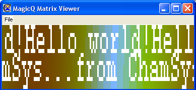
Two text strings can be played back on each layer. The text strings can be positioned at the top, middle or bottom of the grid and can be made to scroll in either horizontal or vertical directions. Text strings can be edited live for real time message applications.
Control text strings from the Text Page (Beam Page 2). Each of the two text strings has a Text Page, a Text, a Text speed and a Text mode.
Using the Text Page and Text encoders select a string that has not been programmed – e.g. Text Page 1, Text 0. Type in new text on the keyboard, press SET and press the soft button associated with the Text attribute. The Input Display will report "text stored".
![]()
The Text mode determines how the text is displayed; horizontally, vertically, top, bottom or middle. The Text speed determines the speed that the text scrolls across the screen.
Note that Text mode values less than 128 cause the text to be scrolled across the screen with no gap between the start and end of the text. Text mode values greater than 128 cause the text to be scrolled with a gap between the end of the text and the starting of the text again. Two different fonts can be selected using the text mode values.
The two sets of text controls enable one text string to be scrolled in one direction and another text string to be scrolled in the opposite direction.
It is also possible to use the single modes to display a single character, a single word or a single phrase from the text string at a time on the screen.
By using the position and size parameters in the Position Window, the character can be placed anywhere in the grid or made to fill the entire grid.
![]()
![]()
When the mode is set to single words then MagicQ displays each word in turn. Each word must be separated by a single space in the text string.
When the mode is set to chunks single chunks then MagicQ displays each chunk in turn. Each chunk must be separated by a single underscore (_) character in the text string. Space characters are displayed normally.
Use the Position attributes of the bitmap layer to make changes to the position of the bitmap / text – set the X or Y position, the X or Y size and the rotation.
You can play back standard FX on the bitmap layer attributes just like you would on a moving head. For example, to scroll a bitmap form left to right, first set the X position to centre (X pos is 128) and then add a Ramp Up to the X pos.
Use the Colour attributes to determine the layers of red, green and blue in the bitmap / text. For LED matrix you may find it is better to use only one colour at a time – for instance, set Red to 255 and Blue and Green to 0.
An iris and a strobe function are also included under the Beam attributes.
It is also possible to use playbacks set as LTP faders in order to control individual parameters of the bitmap from faders.
The FX channels enable FX to be applied to the grid. The FX type selects the FX that is applied. Some of the FX are stand-alone, e.g. lines and rainbows. Others like move and audio FX are applied on top of the selected bitmap or text.
The FX parameters depend upon the FX type selected – but generally FX parameter 1 is the speed, FX parameter 2 is the offset between row or column items in the grid, and FX parameter 3 selects the mode – forward, reverse, bounce or twin.
The currently supported FX are:
Vert lines, Horiz lines – enables lines to be moved across the grid. Modify the mode to change thickness of the lines. Change offset to make patterns rather than lines.
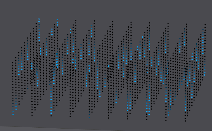
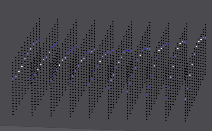
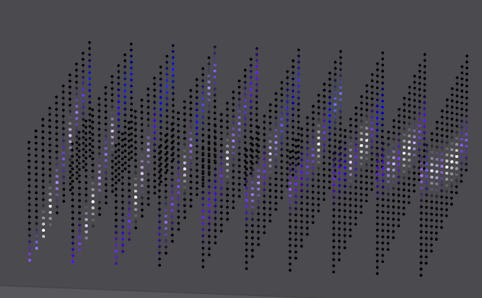
The first image below shows vertical lines with parameter 2 and parameter 3 set to 0. Adjusting parameter 2 gives an offset on the line as shown in the second image. Adjusting parameter 3 changes the width of the line and changes the mode to bounce instead of normal in the third image.
![]()
![]()
![]()
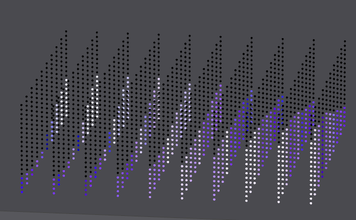
Vert random, Horiz random – enable random movement of elements across the grid. Modify the mode to change thickness of the elements and offset to change the frequency. With this FX it is possible to generate snow and rain type FX.
![]()
Spot random – enable random spots on the grid. Modify mode to determine whether the defaults is white spots on black background or black spots on white background.
![]()
Vert Rainbow, Horiz Rainbow – enable rainbow patterns across the grid. Modify offset to multiply the rainbow across the grid.
![]()
Snakes – enable snaking patterns on the grid. Modify the mode to determine the number of snakes, the randomness of the movement and whether they are white or coloured.
![]()
![]()
Bat’n’Ball – enables simple bat and ball game on the grid. The bats are controlled by FX Parameters 2 and 3. The game starts when one of the bats is moved. Other bitmap layers can be combined with this to make a background for the playing field.
![]()
Vert Move, Horiz Move, Move – moves the selected bitmap or text around the grid. The bitmap will wrap around the edges, thus allowing a texture to be moved across the entire surface of the grid.
Ramp Horiz and Ramp Vert – these perform a ramp across the entire grid in the horizontal or vertical directions. FX P1 parameter controls the speed, FX P2 controls the crossfade and FX P3 controls the width.
Wipe Horiz and Wipe Vert – these perform a wipe of a colour across the entire grid in the horizontal or vertical directions. The colour wiped across the grid is determined by the red, green, blue colour attributes of the Pixel Map layer. It is possible to wipe multiple colours across a grid simultaneously by choosing different colours in sequence. When these FX are in use the red, green, blue attributes do not affect the overall colour of the layer as they would normally.
The Pixel Mapper supports Audio FX – it uncovers part of the selected bitmap, text or movie dependent on the level of the audio input.
![]()
Parameter 2 select the channels to respond to. When set to 0, it uses all 14 audio input channels. From 1 to 14 it selects one channel to respond to. Value 15 selects the left channels, value 16 the right channels.
The mode determines from which grid edge the audio takes effect. The image below shows an audio effect on the internal green, yellow, red bitmap.
The possible modes are:
0 | Graph top | Graphic equalizer down | FX P2 specifies channels |
1 | Level top | Columns left to right | FX P2 specifies channels |
2 | Level bottom | Columns right to left | FX P2 specifies channels |
3 | Level left | Rows top to bottom | FX P2 specifies channels |
4 | Level right | Rows bottom to top | FX P2 specifies channels |
5 | BMT1 | Split into 3 - Mid,Base,Treble | |
6 | BMT2 | Split into 3 - Base,Mid,Treble | |
7 | BMT3 | Split into 3 - Base,Treble,Mid | |
8 | BMT4 | Split into 3 - Treble,Base,Mid | |
9 | BMT5 | Split into 3 - Treble,Mid,Base | |
10 | BMT6 | Split into 3 - Mid,Treble,Base | |
64 | Graph bottom | Graphic equalizer up | FX P2 specifies channels |
128 | Graph bottom/top | Graphic equalizer up/down | FX P2 specifies channels |
192 | Graph top/bottom | Graphic equalizer down/up | FX P2 specifies channels |
In Setup, View Settings, Ports, Audio Input select the audio interface. The Audio Max Level defaults to 0 which indicates a full audio range signal is expected. To boost the audio signal, set the Audio Max Level to the maximum value expected between 1 and 255. If there is a lot of noise then set the Audio Min Level to eliminate the noise.
The interaction of the different pixel mapping layers can be controlled using the Col Mix attribute in the colour page. The types are
When a layer is set to "green key" then any green pixels in that layer pass through the media from the lower layers. Non-green pixels play back the media on that layer. The mask must be pure green.
When a layer is set to "blue key" then any blue pixels in that layer pass through the media from the lower layers. Non-blue pixels play back the media on that layer. The mask must be pure blue.
When any active Pixel Map layer is active (dimmer above 0%) then setting "no base" on that layer will make the Pixel Map effect ignore any base level for the controlled channels instead of adding to the base level.
When any active Pixel Map layer is active (dimmer above 0%) then setting "max with base" on that layer will make MagicQ perform a maximum of the Pixel Map effect and any base level for the controlled channels instead of adding to the base level.
The Colour Page of attributes allows the levels of the red, green and blue attributes to be set independently. The default values are 128, 128, 128. Each colour can be boosted or cut.
The Colour Type attribute allows the overall colour to be adjusted including inverts, mapping of colours, black and white and other colour effects.
Added new apply type to the Pixel Mapper of "use int" and "fit use int". When these apply types are used the Pixel Mapper applies to the intensity channel of the heads in the grid instead of to the RGB channels. If the heads in the grid have no intensity channel then no pixel mapping is applied to the head. This is useful for example to use the pixelmapper on the intensity channel of moving lights or on strobes.
MagicQ supports 3D Pixel Mapping, enabling easy control of LED ceilings, chandeliers and other 3D LED objects. MagicQ supports 3D grids and multiple heads can be inserted into the 3D grid in one go making it easy to create the grid mapping.
In the Output Window, View Plan a grid can be made into a 3D grid by pressing SHIFT and SET GRID DEPTH. This makes the current grid into the starting grid and allocates the following grids to make up the depth. The following grids must be empty (0/0 size) before they can be allocated to a 3D grid. For example, to make a 10x10x20 grid - go to grid 1, set the grid size to 10x10. Then set the grid depth to 20. Grid 1 then becomes a 3D grid using grids 1 to 20. The Grid is shown on Encoder A as grid 1-1 (20) to 1-20 (20). MagicQ no longer shows grids 2 to 20.
Heads can be inserted into the grid in 3D direction as well as the normal way - horizontally or vertically. Pressing INSERT HEADS gives a list of options. When inserting in 3D direction the starting position in 3D is determined by the Grid number. For example if you have Grid 1 as a 10x10x20 grid then inserting a 5 element multi head into Grid 1-1 using 3D Direction will insert it into grids 1-1 to 1-5. If you do the same operation into Grid 1-10 then it will insert into grids 1-10 to 1-15.
The MagicQ Pixel Mapper personality (Generic_Bitmap_With FX 2.hed) has been extended to add extra channels for controlling 3D FX (Generic_Bitmap_With FX 3.hed). In the Outputs Window, View Plan pressing PATCH PIXMAP will now patch the 3D personality (FX3).
3D Pixel mapping effects are selected using the "3D FX Type" parameter under the "3D FX" page in the Media window. For each 3D FX there are a number of parameters (X,A1,A2,A3,B1,B2,B3).
3d FX Types such as Slide, Particle and Particle Bounce generate a 3D effect on a single Pixel Map layer.
There are a number of 3D effects available in MagicQ which can be modulated using up to two other Pixel Map layers as modulation layers - these extra layers modulate the 3D FX according to the intensity of each pixel in the 2D layer. 2D FX can be played on the modulation layers which then affect the 3D layer.
The order of these layers is processed from left to right in the Media Window, with the modulate layers being a lower numbered layer than the 3D effect layer. Typically for these modulate effects, layer 1 will be set to 3D FX Type = Mod Layer 1, layer 2 will be set to 3D FX Type = Mod Layer 2 and layer 3 will be used to select the specific 3D FX such as Height Map, Full Up, Fill Down.
The slide effect slides the 2D frame and slides it either back or forward in the Z axis over time.
3D FX A1 determines the speed and direction of the movement. 0 to 127 being slide up from fast to slow, and 128 to 255 being slide down from fast to slow
The particle FX applies a simple particle system to the 3D grid. The particles take their colour from the Hue/Sat/Brightness colour values in the Col section of the Media window.
3D FX A1 determines the direction, axis and speed upon which the 3D particles travel.
3D FX X determines the spawn probability of a particle if one isn’t currently alive in the column
3D FX B1 applies a random hue to the particles
3D FX A2 applies a "trail" to the particle as it moves.
The col offset uses the colour of the pixels in the 2D frame to determine the offset in 3D.
3D FX A1 allows different colour types to be selected - e.g. using the offset based on red, green, blue or on combinations of colours such as red and blue.
3D FX A2 allows the width to be modified - by default it is set to 50% of the grid depth.
This effect takes the input media from it’s own layer, and uses Modulate Layer 1 to offset the vertical position of the layer in 3D space and the Modulate Layer 2 to change the amount of blur. The vertical position and blur are calculated per column, so wave effects can be applied by using the "Organic" 2D FX on the Modulate 1 layer.
3D FX A1 applies a constant height offset to the entire grid on top of the Modulate Layer 1 amount. 3D FX B1 applies a constant blur amount to the entire grid on top of the Modulate Layer 2 amount.
The "Fill up" and "Fill down" modes fill the rest of the 3D space either above or below the media layer with the same pixel value.
The particle bounce effect can be likened to a grid of balls, where changes to the Modulate Layer 1 values are used as a "kick" to the ball upwards.
Using this method, you can use a flash button to flash on the Modulate Layer 1, and the particles will flick up, and then fall back down again under a simulated gravity. Alternatively using the Audio Input to MagicQ, use a bass beat to bump the particles in the grid.
Only when a particle is stationary will it receive a "kick". If the particle is still in mid air, it will continue to fall under the effects of the simulated gravity.
A larger change in value to the input will result in a larger velocity.
MagicQ has the ability to run Pixel Map FX over a Group of heads, based on the grid associated with that group without the need to patch a more advanced pixel map.
Each group has a grid associated with it by default. To edit the layout of the heads within the group grid select the "View Grid" soft button at the top of the group window.
Within the Output Plan window the heads for the previously selected group can be arranged to use with Simple Pixel Map FX.
Group grids can only contain heads that are within the Group.
To apply a Pixel Map FX simply select a group, press the ADD FX soft button and select from the Pixel map category.
Pixel Map FX can be run over any attributes of the heads within the group.
![]()
Pixel Map FX honour the grid arrangement of the group and apply the FX across the grid the same way as the more advanced pixel mapper would. Updates to the grid arrangement will in turn update any Cues using a Pixel Map FX.
The PixMap FX in the standard FX generator have now been enhanced with new apply type options. In addition to the existing RGB and individual attribute, it is now possible to select Pos Palette, Col Palette and Beam Palette.
When a Palette apply type is used then the pixelmap FX pattern is applied using the palettes rather than using hard values.
For example, if you choose a Vert Line FX then applied to Intensity then line would be applied to the Intensity. If, instead you chose Colour Palette and then select Palettes Red and Green then the the FX would apply the Red and Green palettes - the first Palette Red would be used for all cases where the FX level is 0, whilst the Palette Green would be applied where the level was 100% - i.e. the vertical line. Pixels where the FX is fading inbetween 0% and 100% would interpolate between the Red and Green palette.
Any attributes can be put into the palettes, so a Position Palette could include Position and Zoom - enabling an effect with one Palette up and tight zoom and another Palette down with wide zoom.
The Palettes can be changed in the Prog, FX and Cue FX window as for normal FX Palettes.
In versions prior to v1.9.3.0 MagicQ had one inbuilt PixelFX that used Palettes - Pix2Col. This performed a vertical line or horizontal line on 2 Palettes depending on the size of the Group Grid. This is still supported - but a wider range of effects can be used using this new Palette selection - for example, a PixCircle can be applied to two palettes.
The PixMap FX in the standard FX generator can now be applied to any Grid, not just to the Grid for the selected Group.
This enables PixMap FX to be applied to multiple Groups. It also avoids the need to create multiple different Group Grids - a single User grid can be configured for the whole lighting rig and then Pixel FX can be run over the required groups within that Grid.
The Grid can be changed live in the Prog, View FX and Cue, View FX windows from the Grid ID field.
It is possible to play back patterns specifically on multi element heads such as Chromlech Jarags (5x5 dimmers) or other LED tile squares. If the Pos FX is set to "Mult head" then any media, text or FX on that layer will apply to the individual multi element heads rather than across the entire grid. The same "image" will be placed on all the multi head elements. For best results the grid should be made of same size heads with equal spacing.
Sometimes it is useful to make a grid of groups rather than a grid of individual heads – for example you may have a large amount of LED broken down into panels which you have then programmed as groups.
Grids of groups enable multiple heads to be allocated to one box in the grid. When Bitmaps, Text or internal FX are played back on the grid, then all heads in a group will take the colour/level associated with a particular box in the grid.
Use Soft Button B "Grid Type" to select "Groups" instead of "Heads".
The auto groups function in the Outputs Window, Plan View has an option to generate groups for each of the multi element heads in the chosen grid.
These groups can then be use in a grid of groups to perform intensity and colour chases across all the multi heads. By using the first layer for the grid of heads, and the second layer for a grid of groups with colour mode set to multiply the FX on the individual multi heads and the FX on the complete heads can be mixed together.
To program LED heads using standard FX rather then the bitmap layers, just select the heads and program them like moving lights.
Select the group of LED heads, e.g. "All Pixeline", set the master intensities using the encoders or by pressing the DIM @ FULL soft button in the group window.
You can select standard in-built FX for LED heads in the Beam window.
To program colour chases across all patched RGB pixels select all the RGB heads and then in the Colour Window select your base colour, e.g. Red at 128, Green at 128, Blue at 128. Then play back an FX on the head such as rgb, cmy or pulse4steps. Speed and size are controlled as normal.
Press the Auto Group button to automatically generate groups based on the grid size. This generates groups using the entire grid but with different orders of selection, e.g. from centre to outside, from the edges, and vice versa. This makes it easy to quickly generate different FX.
![]()
Using the auto groups, it is then possible to use standard FX such as RGB, sine waves, pulses to generate FX on your grid.
![]()
![]()
It is possible to make a group out of the currently selected items within the Grid. For example, use CTRL + select a few items and then press SHIFT + MAKE GROUP to make a group i nthe Group Window for all those items.
To get the best out of a large array of pixel heads it is best to make groups. Select all the RGB pixels for a particular head and record it as a group. The order in which you select the heads determines the order that FX are played back on them. You can reverse the selection of an entire group by pressing the top right soft button in the Group Window.
If you have set up a Grid in the Plan View then you can easily select the pixel heads from this View before recording the group in the Group Window. Use Auto Groups to generate groups in different directions on the group and from the centre outwards.
In the Plan View use SHIFT + MAKE GROUP to make a group from the currently selected heads. If no text is entered before pressing MAKE GROUP the group is automatically named based on the first and last head numbers in the group.
To get a colour rainbow to roll seamlessly across a line of led battens you may need to reverse the selection of the individual groups - it depends which way you numbered your LED heads.
MagicQ has an in-built personality editor, so it is easy to create new personalities. New personalities can be based on other personalities or created from a blank personality.
For simple LED heads you may be able to use one of the generic LED personalities - either generic LED 3 chan or generic LED 4 chan.
When creating a personality allocate the red, green and blue channels to the cyan, magenta and yellow attributes.
From v1.9.4.2 Output grids can be output to external monitors as pure pixels for driving LED walls directly via HDMI/Display Port directly rather than via network protocols such as ArtNet and sACN. This provides an alternative to using MagicHD for lower resolution installations.
In the Output Window, View Grid set the VIEW TYPE to Pixel. The Output window will then show as pure pixels - 1 pixel per Grid cell.
Zooming is supported to increase the number of pixels covered by each Output Grid cell. Soft button F can be used to zoom the Grid to fit to the window size.
When the Output Window is placed on an external monitor it will show without title bar and borders - i.e. pure pixels output from the Pixel Mapper.
When using this feature it is recommended to use Output Windows 2 or 3 and to fix them to the external monitors, by setting them as the Fixed Window for the required monitor in Setup, View System, View Monitors.
| | ||