| |
| |
On MagicQ consoles hold the power button on the rear panel. On MagicQ PC and Mac click on the MagicQ application icon.
On start up you are presented with an option to load demo shows or to continue the last show. Selecting last show will load and run the last show used on the system. This option can be hidden for subsequent start ups.
The console remembers all windows that were open when the console was last used. To close all windows press SHIFT and CLOSE.
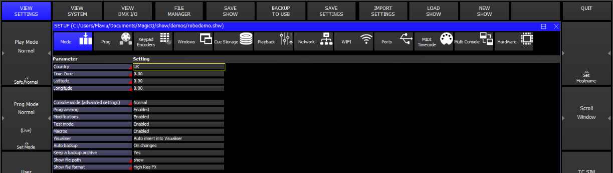
Press SETUP to open the Setup Window.
On MagicQ consoles if the touch screen does not seem to be responding to your touch correctly then you may need to calibrate the touch screen.
Press the SETUP button to open the Setup Window. Press the CAL TOUCH soft button. When asked for confirmation press 1 on the keypad or press the CAL TOUCH soft button again.
Calibration works by finding the bottom left and top right corners of the screen. First press the bottom left of the touch screen and then the top right. You may wish to use a fine but blunt object.
The shortcut CTRL + SET can be used to open the Calibrate window at any time.
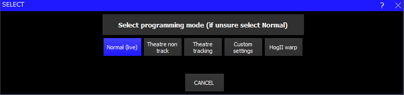
To start a new show, go to the Setup Window and press the NEW SHOW soft button. This will clear the current show from memory – shows that have been previously saved to disc will not be affected. You will be asked to confirm by selecting YES.
There is a choice of six modes.
The mode can be changed at any time by using the Programming Mode soft button in the Setup Window. In addition each individual option / default value can be customised by the user and saved as their personal settings file.
Starting a show clears all patching, all programming and all palettes. It does not clear console specific options such as the configuration of the DMX outputs or the calibration of the touch screen.
See <_programming_mode,Programming Mode> for more details.
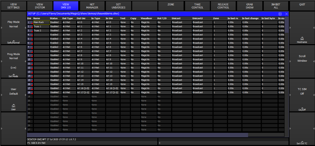
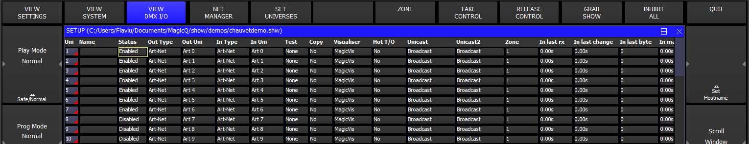
To enable output of channel data select the DMX IO VIEW in the Setup Window. This window enables modification of the inputs and outputs for all the universes. MagicQ consoles support DMX directly from the console or via an external Ethernet to DMX convertor. On MagicQ PC or Mac you can output via USB to DMX interfaces (such as MagicDMX) or via DMX outputs from the Wings.
All current MagicQ consoles have DMX output ports directly on the rear panel.
The four DMX outputs on the rear panel automatically output universes 1 to 4 unless they are configured otherwise. The DMX will be output regardless of the "Status" enabled or disabled in the Setup DMX I/O window. On Pro consoles there is a green LED on the rear panel that indicates when DMX is being output.
If you wish to choose alternative universes to be output to the four DMX outputs on the rear panel then you will need to configure the outputs manually. For each of the Universes you wish to output on the rear panel, select Out Type as "MagicQ Direct" and Port 1, Port 2, Port 3 and Port 4 and enable the universes.
The picture below shows the direct ports to output Universes 5 to 8.
MagicQ supports output via the network ports using Art-Net, Pathport or ACN Streaming DMX.
To output Art-Net on a Universe enable it and ensure that the output type is set to Art-Net. Choose which Art-Net Universe you wish to Output the MagicQ Universe on. MagicQ defaults to outputting MagicQ universe 1 on the first Art-Net Universe (Art 0-0).
If you are using Ethernet to DMX512 conversion boxes then you will need to configure the boxes to respond to the correct Art-Net sub-net and Art-Net universe.
With ChamSys SnakeSys B4 or R4 you need to set up the two rotary switches to the correct values – the left one for Art-Net sub-net and the right one for Art-Net universe. The interface will then decode the four Art-Net universes starting from that Art-Net subnet and universe.
In most networks the Art-Net sub-net is set to 0. If you are using only one Ethernet to DMX512 interface then you can normally use subnet 0 universe 0.
If you are using multiple Ethernet Interfaces then you will need to set each Ethernet Interface to a different Art-Net Universe – for example when using two ChamSys SnakeSys B4 Interfaces set the first Interface to Art-Net Universe 0 and the second one to Art-Net Universe 4.
MagicQ includes a DMX viewer for monitoring Art-Net on the Network – select Tools, DMX View.
To connect a MagicQ Playback or Extra Wing, simply connect the Wing to the MagicQ console via USB. In the Setup Window, View System, View Wings set the first Wing to be type USB Wing.
By default the Playback Wings are set so that the Wings change page when the Next Page / Prev Page button are pressed on the MagicQ console. It is possible to make the Wings operate completely independently of the main MagicQ console by changing the "Lower Bank Tie" and "Upper Bank Tie".
To use multiple Playback Wings simply connect them and change the type to USB wing. Note not all Wings connect to all MagicQ consoles. The Stadium Connect can only connect to a computer, and the MQ500M Stadium Wing, only connects to the MQ500M.
When using MagicQ consoles with multiple Playback / Extra Wings (or multiple Execute Wings) a Wing ID can be set for each Wing. The required wing ID can then be set in Setup, View Wings to ensure that the Wings are identified correctly and control the correct Playbacks.
Hold down the lower NEXT PAGE and PREV PAGE buttons when powering on the Wing to get into the Wing config mode. From the menus you can then set a Wing ID.
All Extra Wing Compacts, and Extra Wings and Playback Wings manufactured since 2012 support setting of Wing ID. Older Extra Wings including those with yellow displays do not support Wing ID.
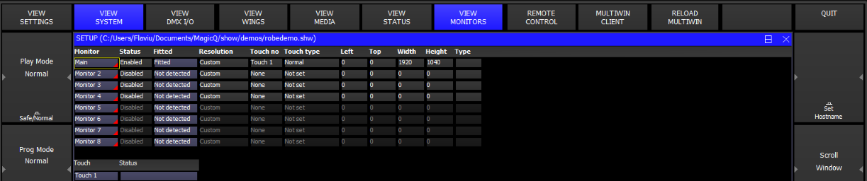
MagicQ consoles have DVI or HDMI connectors for connecting external monitors. The monitor should be plugged in before starting the console.
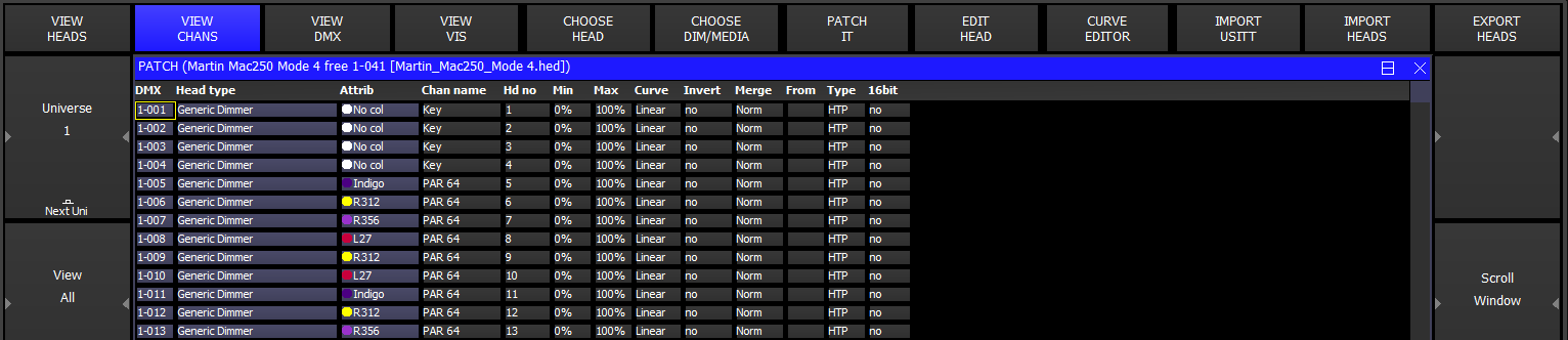
Open the Patch Window by pressing the PATCH button. The Patch Window has four views, VIEW HEADS, VIEW CHANS, VIEW DMX and VIEW VIS. In this section we describe patching in VIEW HEADS.

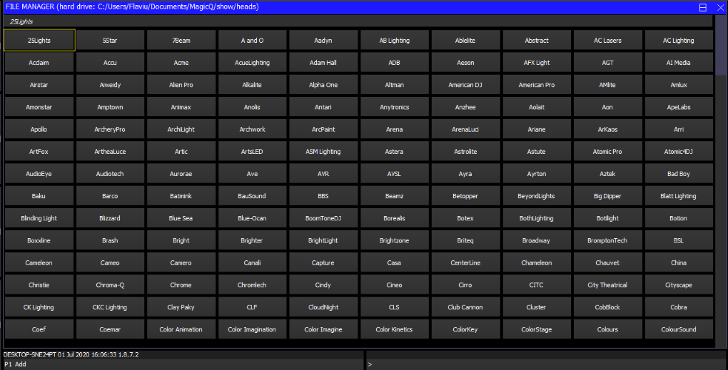
Choose the fixture you wish to patch by pressing the CHOOSE HEAD soft button. The Window will change to give you a list of manufacturers and fixtures. Select a fixture by pressing the touch screen. Alternatively scroll around the Window using the cursor keys, and press ENTER when the cursor is over the correct fixture.
Once you have chosen the fixture, a window will view different mode options. Select the correct mode the fixture is being used in.
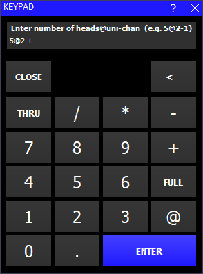
You will then be returned to the Patch Window. Press the PATCH IT soft button to patch the fixture. You will be prompted for the number of fixtures you wish to patch and the universe and address where you wish to patch them to. Use @ to patch at a specific universe and address.
For example to patch 12 Chauvet Professional Maverick MK3 Spots in advanced (39 channels) mode, at universe 1 start address 1:
12 @ 1 - 1
If you wish to patch multiple channels at fixed offsets e.g. 3 Chauvet Professional Maverick Silens 2 Profiles on universe 2, with an offset of 35 channels between each fixture:
3 @ 2 – 1 / 35
Patching multiple fixtures in any of the theatre modes is slightly different. When starting a new show, if you choose ‘Theatre Track’ or ‘Theatre non track’ some of the programming settings will change. patching requires the fixture (or head) number @ universe number – channel number. For e.g. if you wanted to patch in 3 standard dimmers, on universe 1 and start channel 1 you would use the THRU button and type in the following: 3 > 1@1-1
To patch a dimmer, simply press CHOOSE DIM/MEDIA, select Generic Dimmer and then patch one or more dimmers as above.
In the Patch Window there are columns that can be configured, such as the DMX address, head name and head number. To modify, select the data in one of the columns, then input the new value using the keypad, and press ENTER.
Once you have patched all the Fixtures you can then name and number them as you wish. It is recommended that you name the dimmer or the fixture based on its location (e.g. front wash / back truss SL). For dimmers you may wish to configure the gel. This makes programming easier – enabling the console to auto program cues for you.
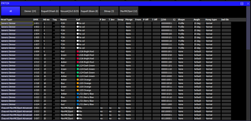
The gel field uses gel numbers. For Lee colours enter the gel number directly (e.g. 181 for Lee 181). For Rosco colours enter the gel number preceded by a dot (e.g. .14 for Rosco 14). For no colour enter 0. If you would prefer to use colour names rather than gel numbers then simply enter the colour name.
To test a patched head or dimmer, simply press the TEST MODE soft button (soft button encode C) and the head which the cursor is over will be tested. For heads it locates the whole head; for dimmers it sets the dimmer to 100%. Press the TEST MODE soft button again to turn test mode off.
In order to control intelligent heads it is necessary to be able to select which heads to use. The MagicQ console keeps track of the currently selected heads to enable it to determine which heads to apply changes to. The operator can select head individually or can use groups to recall configurations of heads that are used frequently.
In "Hog Warp" mode or when the Setup option "Keypad always selects head is set" you can select heads from the keypad – for instance to select heads 1 through 4.
1 THRU 4 ENTER
In other modes, you can select the heads using
1 THRU 4 @@
The console automatically generates a group for all the heads of a particular head type. In addition new groups can easily be recorded.
The Group Window has two views. VIEW GROUPS enables selection of heads using groups whilst VIEW HEADS enables individual selection of heads.
In VIEW GROUPS, pressing the touch screen for a particular group selects all the heads associated with that group. All other heads are deselected. To select multiple groups, press SHIFT and a group to toggle the group in and out of selection.
In VIEW HEADS, individual heads are selected / deselected by pressing the touch screen. Use PG UP and PG DN to scroll through the heads.
Select the heads you want in a group using keypad selection or in the VIEW HEADS view of the Group Window.
Change to the VIEW GROUPS view.
Press RECORD and then select the group you wish to record either by pressing the touch screen or by using the cursor keys and then pressing ENTER.
When recording a group, if you key in a name before pressing the touch screen (or pressing ENTER) then the group will be named at the same time as it is recorded.
You can name a group at any time by keying in the name, pressing SET, and pressing the touch screen.
If you do not have a keyboard then press SET and select the group to name by pressing the touch screen (or using cursor keys and ENTER). A keyboard window will be displayed for you to enter the name on screen.
Once a group has been recorded then pressing the touch screen for the group will make all the heads in the group selected. All other heads will be deselected. Use SHIFT to select multiple groups. There is a Setup option to allow the user to default to selecting multiple groups.
From the keypad you can enter commands such as
1 @ 50 ENTER
1 THRU 4 @ FULL ENTER
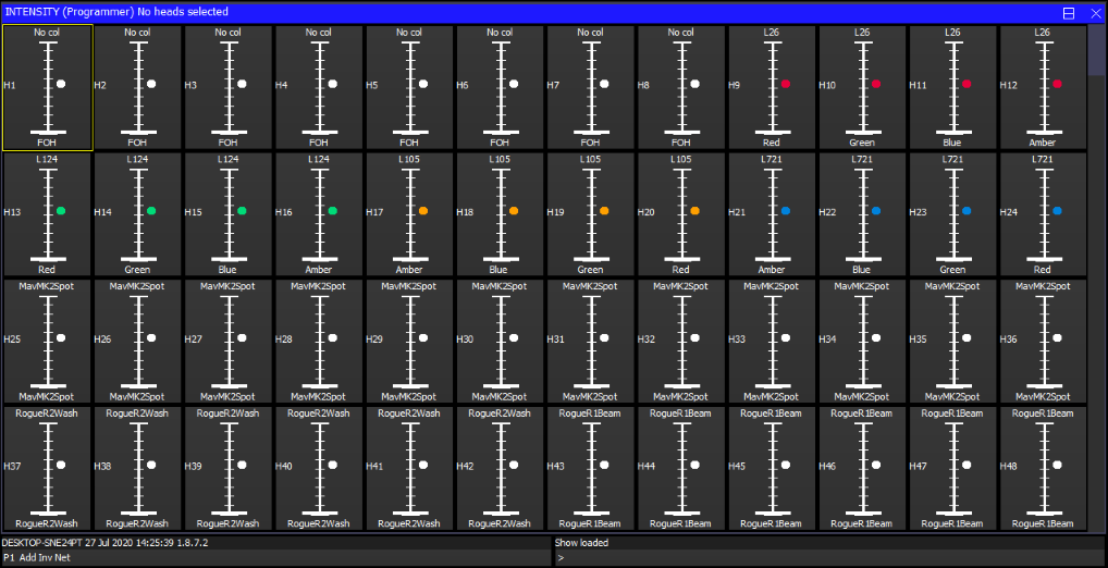
It is also possible to use the Intensity Window by pressing the INT button. This window displays a fader for each dimmer and head patched onto the console. Pressing the slider part of the fader sets the appropriate level. When a fader is moved from 0 the channel in the programmer is activated – and the fader will turn red.
The Window has two views, View Prog and View Preset – faders changed in the Prog View affect the intensity levels in the programmer and are recorded into Cues. Faders changed in the Preset View are like traditional "one per channel" preset faders on older lighting consoles – this enables levels on channels to be set without affecting programming. This is equivalent to "Parking" on other consoles.
The SQUARE OFF soft button enables fast programming of intensities. Using the touch panel select the channels you wish to have at full and at zero – but don’t bother being exactly accurate with the level of the selection. Pressing SQUARE OFF finishes the job by setting all channels that are less than 50% to 0 whilst setting channels above 50% to full.
Use the ALL TO FULL and ALL TO ZERO buttons to change the level of all the channels.
Press the CLEAR soft button to clear the programmer.
The first action you are likely to want to do is to locate the heads – i.e. to put them into a starting position. Select the required heads and then press the LOCATE button. Locating a head brings all the attributes for that head into the programmer.
If the heads enable DMX control of the striking of the lamp then you may need to "Lamp On" the head in order to see the beam. Select the heads and then press SHIFT LOCATE. This runs the "Lamp On" macro.
Intelligent heads have several different attributes typically including pan and tilt, colour, gobo and iris. When the MagicQ lighting console patches an intelligent head it maps the head parameters to standard attributes to enable easy access of the features of the head.
Attributes are categorised into four types – Intensity, Position, Colour and Beam. On MagicQ there is a window for each of these attribute types. Select the required heads, then open the required window.

You can quickly open all the Palette Windows by pressing Layout 1 or holding CTRL and pressing the top soft button marked Palettes – this opens the windows in the layout below.
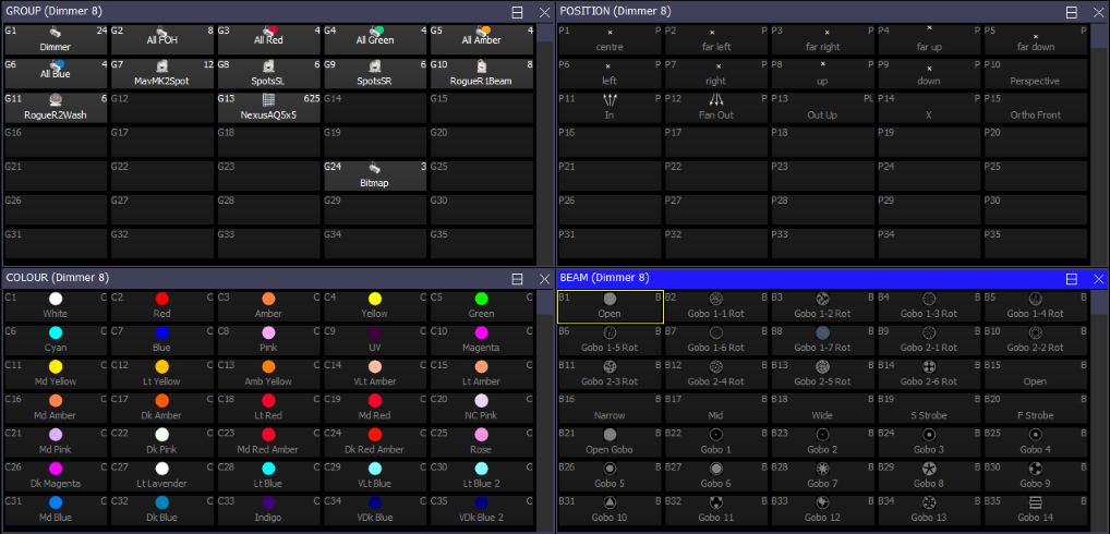
The highlighted window enables controls the soft buttons and rotary encoders. In each of the Windows the X and Y encoders control the most important attributes – Pan and Tilt in Position Window, Col Wheel 1 and Col Wheel 2 in the Colour Window and Gobo Wheel 1 and Gobo Wheel 2 in the Beam Window. In the Beam Window there are more than eight attributes to be controlled – these are accessed using multiple pages of encoders – by pressing the NEXT PAGE soft button.
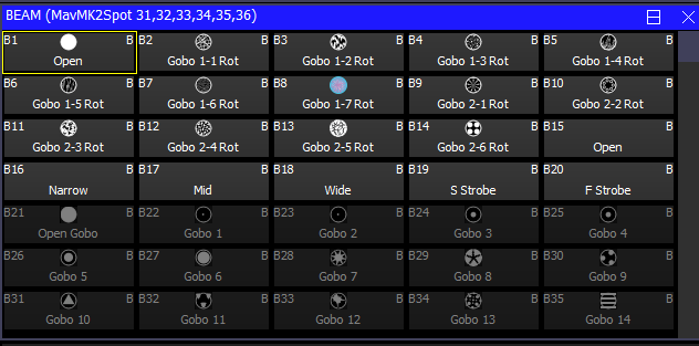
For indexed attributes such as colour wheels and gobo wheels, the button associated with each encoder can be used to bump the attribute value to the next range. Pressing SHIFT and the button bumps back to the previous range.
In addition the window enables selection of palette values for the attribute type using the touch screen. When heads are recorded the system automatically generates palettes for each attribute type. You can record new palette entries, or modify existing ones as you see fit.
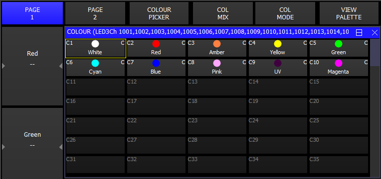
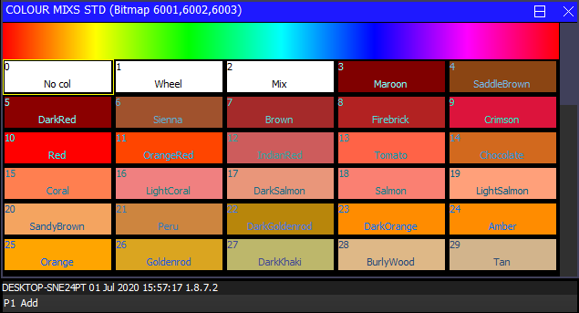
In the Colour Window pressing the COL MIX / COL ATTRIBS button changes to the colour picker. Press COL TYPE to select standard colours, Lee colours, Rosco colours or HIS model.
To record a favourite combination of attributes into a palette (e.g. a rotating triangle with a prism on a MAC500), first modify the attributes to the values you wish to record. Then press RECORD and select the palette entry you wish to record. By default only selected heads get recorded into a palette (this can be changed by pressing SHIFT + RECORD and choosing Record options).

To name the palette, key in the name on the external keyboard, then press SET and select the palette entry you wish to name. To use the on screen keyboard, first move the cursor over the palette entry, then press SET and key in the name followed by ENTER.
To add a FX to some heads, select the heads then from the Group Window or the Prog Window press the ADD FX soft button. Choose the FX to add.
Once you have chosen a FX you are returned to the Prog Window. Use the encoders to modify the parameters of the FX such as the speed, size and spread between heads.
You can add multiple FX to a head, provided that the FX uses different attributes - e.g. you can mix a Pan Sine with a Tilt Sine.
To record a look onto a Cue, first set up the look, then press RECORD and press the S button of the Playback to record the Cue onto.
To test the Cue, first clear the programmer by pressing CLEAR then raise the Playback fader or press the Playback flash button.
Note that recording a Cue onto a Playback, generates a Cue Stack with a single Cue. However, as there is only one step, it behaves as though it is just the Cue on the Playback.
To view a recorded Cue, press the S button for the Playback, and then press CUE to open the Cue Window.
To configure options when recording, press SHIFT + RECORD and a toolbar of record options will be displayed. Choose the options you require then press the S button of the Playback as above.

Recording a Cue Stack is the same as recording a Cue - you simply record multiple Cues onto a Playback and you end up with a Cue Stack.
So, for example to record a stack of two looks, the first yellow dots, the second blue triangles:
To test the Cue, clear the programmer by pressing CLEAR then raise the Playback fader or press the Playback flash button.
View the Cue Stack by selecting the Playback and pressing CUE STACK to open the Cue Stack Window.
When you record more than one Cue onto a Playback the Cue Stack controls the transition from one Cue to another. In Normal mode by default the Cue Stack operates like a chase - i.e. each Cue is executed in turn, with timing being handled by a Chase Speed for the whole Cue Stack.

In Theatre Modes the default timing is Cue Timing – individual Fade times on each step with GO stepping from one step to the next.
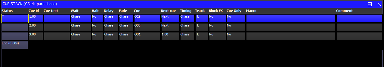
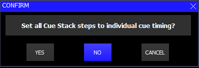
The timing mode can be changed, so that the Cues play back in a theatre style using the GO / STOP buttons. Select the VIEW OPTIONS view and press the CUE TIMING and CHASE TIMING soft buttons to modify the timing mode.
The console enables complete window layouts to be recorded and selected. The console incorporates several standard window layouts including Palettes and Cue Stacks.
There are physical buttons for Layout 1, 2 and 3. Layouts 1 to 12 can also be accessed by holding CTRL and selecting one of the top soft buttons.
To select a Window layout press one of the Layout buttons, or hold down CTRL and select one of the top soft buttons.
To record a Window layout first close all windows (SHIFT + CLOSE). Then open the required Windows and size them appropriately. Press RECORD and then press a Layout button or hold down CTRL and select one of the top soft buttons.
To name the Window layout, press SET and then press a Layout button or hold down CTRL and select one of the top soft buttons. Enter a name for the layout.
When programming a show the show is stored in memory. In order to store your show on the disk you need to press the SAVE SHOW soft button in the Setup Window.
Whilst programming, you should regularly save your show, so that if the power fails your show data is not lost. You can chose any filename - MagicQ will automatically set the file extension to .shw.
By default, MagicQ periodically saves a backup of your show to disk. It uses the same show name but with the file extension .sbk.
It is a good idea to save your show to different file names so that you have various points you can back-track to if things go wrong. For example, save the show as myshow-patch.shw after you have patched and then as myshow-final.shw after you have finished programming.
When you shut down MagicQ through the QUIT soft button in the Setup Window, MagicQ automatically saves a backup copy of your show with a .sbk extension. When you subsequently restart MagicQ this file will be re-loaded. This ensures that MagicQ starts up as it was when the QUIT soft button was pressed.
MagicQ show files are typically only a few megabytes in size so many different shows or versions of a show can be saved without problem.
Now you have Cues and Cue Stacks recorded you can play back your show using the Playback faders and buttons. You can control how each Cue Stack is played back using the Cue Stack options – for example you can set the fader to control LTP fades or FX size and speed.
Make sure the master faders are raised!
Note that if you have a large show file you may wish to turn auto backups off during playback. Remember to turn them back on when you are programming.
If you get stuck at any point, just press the HELP button!
| | ||