| |
| |
On MagicQ you can view the Outputs in many different ways. MagicQ supports up to 4 different Output Windows. This allows four different output views to be viewed simultaneously.
Press the OUT button to open the main Output Window. Press 2 and then OUT to open the second Output Window, 3 + OUT for Output Window 3 and 4 + OUT for Output Window 4. The 2nd Output Window – the Output Info Window can also be opened by pressing CTRL + OUT.
In the Outputs Window, just as in the Programmer Window and Palette View Window there is auto ordering of heads. MagicQ orders the heads according to the selection order. When no heads are selected the order is the normal head order. Auto ordering can be turned off in the Setup Window under Windows, "Auto Row ordering".
The Outputs Window has many different views – press the soft buttons on the top left hand side to change the views.
The Heads View shows information for all of the heads patched in the show - press the VIEW HEADS soft button.
The sort order of the heads is as chosen in the Patch Window, Sort Head. If the Setup option, View Settings, Windows, Auto Row Ordering is set to "yes" then the sort order is modified to show the currently selected heads at the top.
The Output values shown are the values calculated internally in MagicQ BEFORE any patch adjustments are made such as dimmer curves, offsets, inverts, merges, min and max and vdims.
Press CTRL and SHIFT to see the 16bit raw DMX output values.
You can request only information for certain heads to be shown by using the PROG ONLY, SEL ONLY and SEL PB soft buttons. These show respectively, heads that are active in the programmer, selected heads, and heads in the current cue on the selected playback.
You can choose what information is shown for the heads using the VIEW VALS, VIEW RAW and VIEW PLAYBACK and VIEW CUE IDS soft buttons. VIEW VALS shows the values including range and palette names. VIEW RAW shows the numeric values. VIEW PLAYBACKS shows which Playback is controlling the attribute and VIEW CUE IDS shows which Cue ID in a Playback is controlling the attribute.
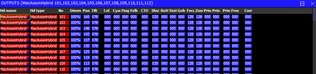
The following colours are used:
Red: Attributes that are in the Programmer
White: Attributes under control of a Playback.
Blue: Attributes controlled by the currently selected Playback
Grey: Attributes not under control of Playbacks or Programmer
The Intensity View shows just intensity information for the patched heads enabling a large number of heads to be shown within the window. Press the VIEW CHANS and VIEW INT soft buttons. Intensity level is shown as a percentage (%).
The sort order of the heads is as chosen in the Patch Window, Sort Head. If the Setup option, View Settings, Windows, Auto Row Ordering is set to "yes" then the sort order is modified to show the currently selected heads at the top.
The Output values shown are the values calculated internally in MagicQ BEFORE any patch adjustments are made such as dimmer curves, offsets, inverts, merges, min and max and vdims.
Use the VIEW HORIZ soft button to change whether heads are shown horizontally or vertically.
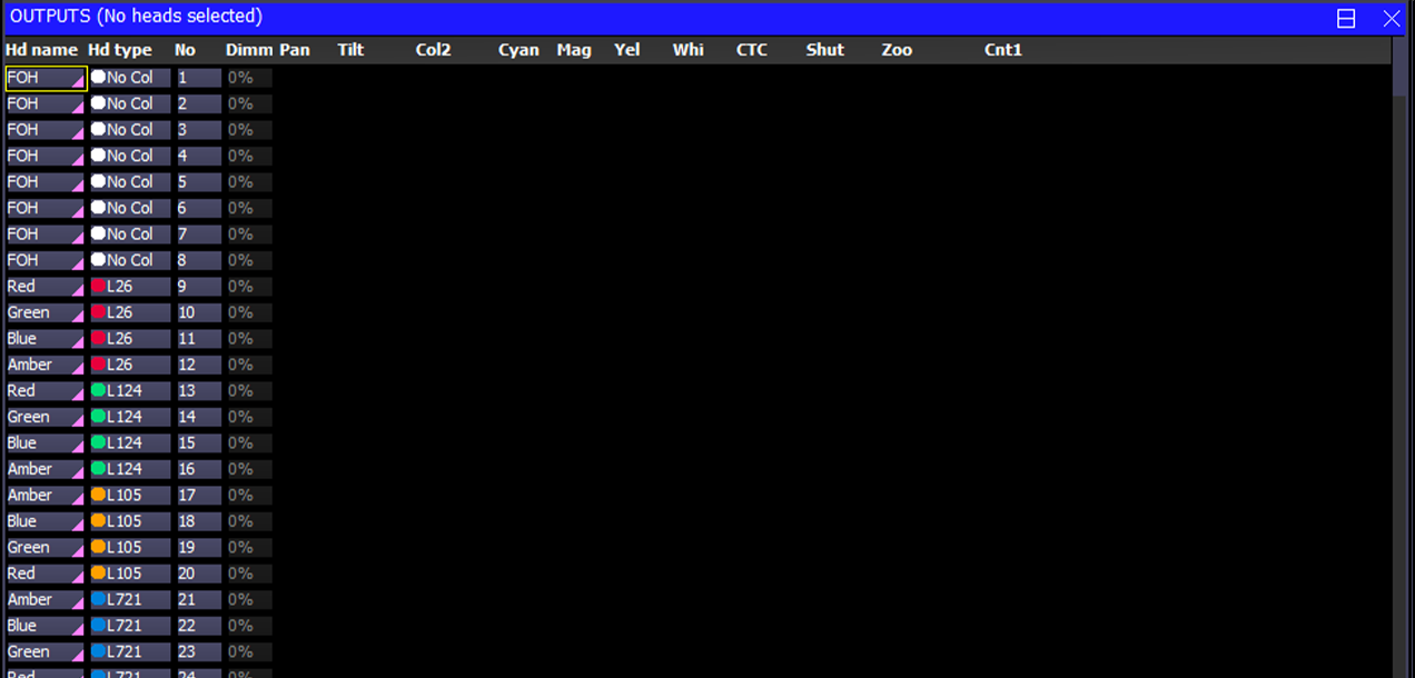
The VIEW NAMES soft button allows names to be shown. Deselect this option if you wish to maximise the number of heads shown in this window or you wish to have a more traditional theatre channel list view.

The VIEW COLS soft buttons allows colours to show the state of the channel.
Red | In programmer |
Cyan | Increasing value |
Green | Decreasing value |
White | Static value controlled by Playback/Cue |
Magenta | Tracked value |
The DMX Channels View shows the actual values that are being output on the DMX or on the network. Press the VIEW CHANS, VIEW DMX and VIEW VALS soft buttons. Note that these values are the real output values – if the output is enabled then these values will be the values transmitted in the DMX packets on the wire. Inversions, merging, and all other modifications are made to the values before they are displayed in this Window.
Intensity channels are shown in red, position in green, colour in purple and beam in yellow. Channels that are not patched are shown in grey.
Use the View Names option on soft button B to make it easier to find specific DMX channel outputs.
Use the VIEW INPUTS / VIEW OUTPUTS soft buttons to view the DMX / network values that are being received rather than the ones being transmitted.
When viewing the Inputs it is possible to select the VIEW MIN MAX soft button to show the maximum values received. Deselecting the VIEW MIN MAX resets the view.
VIEW ART-NET changes to a view of the first 256 Art-Net universes with a count of the number of Art-Net packets being received on each universe per second. From v1.7.1.3, counts in red show an Art-Net universe where there is a conflict from 2 or more consoles.
Press the VIEW CHANS, VIEW DMX and VIEW MOVE soft buttons for movement view.
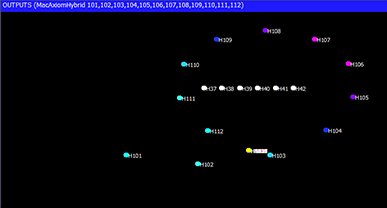
The movement view shows the relative positions of heads in terms of pan and tilt range on a 2D map. It also shows the current colour of the heads. This enables previewing of FX and relative positions without the lighting rig. Press the VIEW CHANS, VIEW DMX, VIEW MOVE soft buttons.
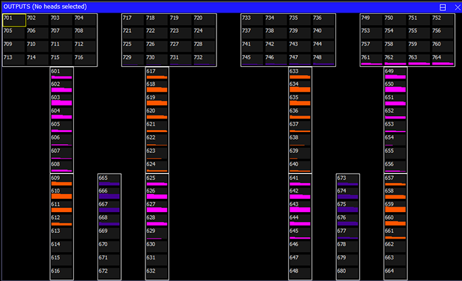
Press the VIEW CHANS, VIEW DMX and VIEW CHART soft buttons for chart view.
In this view whole universes of DMX are shown in a graphical format. Use Encoder A to change the starting universe.
Press VIEW INPUTS to view the DMX inputs to the console instead of the outputs.
Plan View enables 2D plans of the stage rig to be constructed and viewed. It also enables grids of LED or dimmers to be created for use with the in-built pixel mapping (Bitmap FX) engine. Press the VIEW PLAN soft button.
It is possible to create a rig plan in the Outputs window, so that you can easily identify the levels and colours of your moving lights based on their position in the lighting rig. The model of the rig in MagicQ consists of a grid - each cell can be assigned to a particular head number.
In the Outputs Window, select View Plan. Then select View Grid and View Hd Nos. Press Grid Size and enter a matrix size for your lighting rig – e.g. 30/20 gives a 30 column by 20 row grid.
If grid width is specified then MagicQ will choose a height to keep the aspect ratio for the background bitmap, or if none to match the width.
A grid is now displayed. In each of the boxes enter the head number of the head that you wish to be represented in this box. In order to make best use of this feature all heads should have unique numbers.
The grid can be zoomed on encoder E. Hold ALT to zoom horizontal only.
Soft button E can be used to zoom into the current cursor position and to reset back out to 100%.
Background images can be added via the Grid Action soft button.
You can use SHIFT or CTRL and the cursor keys to cursor select a number of items and set a sequence of head numbers starting from the entered head number. The order of the cursor selection determines how the items are ordered - for example, cursor selecting an area from bottom right to bottom left and then to top left will cause the heads to be number from bottom right to top left starting horizontally.
Note that it is not necessary to have a head number assigned to every cell in the grid – cells can be blank. This enables the lights to be positioned in the grid in a corresponding way to how the heads are positioned on the rig.
To remove a head number from a cell, press REMOVE and select the cell. Move and Copy can also be used to quickly move or copy one or more cells.
To enter an element of a Head enter <Head No> . <Element>
When setting Head Nos into a Grid with Grid Options Multi Element MagicQ now sets Head Nos according to whether an element is specified or not. Head Nos without elements are set as single Heads in the grid whilst Head Nos with elements are set as mul;ti element Heads in the Grid. For example, setting Head No 10 will insert just the Head 10 in a single cell, whilst setting Head 10.1 will insert all the Head Elements into cells as per the element layout of the Head.
The Grid Option "All Multi" forces Heads with multiple elements that are entered as a Head No without an element specified to be inserted as all elements in a Multi Element grid.
You can use the INSERT HEADS button to insert the currently selected heads into the grid. The heads are placed in order of head number. If no heads are selected then all heads from the patch are inserted.
The Insert Heads soft button has the options Horiz, Vert, Dup Ele (Horiz), Dup Ele (Vert), 3D and and Col Web.
Horiz, Vert insert into the Grid in the horizontal or vertical direction. Multi element heads will be inserted into separate grid cells according to the width and height specifiers in the personality and using the shape from the personality to determine the orientation of the multiple elements. Duplicate element heads will be inserted as a single cell.
Dup Ele (Horiz) and Dup Ele (Vert) are used to insert all the elements of a Duplicated Element head into the grid as separate cells. The duplicated elements will be inserted into separate grid cells according to the width and height specifiers in the personality and using the shape from the personality to determine the orientation of the duplicated elements.
Note that Horiz and Vert refer to the relationship between separate heads, not the orientation of the multi elements or duplicated elements within a head. To rotate a multi element or a duplicated element head to an orientation that is different to that specified in the personality, use the Output Multi Head Support below.
3D is used for inserting for 3D pixel mapping in the 3rd dimension - only multi element heads can be inserted in 3D.
Col Web is for inserted Colour Web only.
The Output Grids supports manipulation of multi element heads and duplicated heads as complete objects. When setting a grid size for the first time MagicQ prompts whether to use multi heads or not. The option can be changed at any time by pressing the GRID OPTIONS soft button and selecting Set Multihead or Clear Multihead.
In Multi Head mode, MagicQ automatically keeps tracks of the elements of the the multi element or duplicated heads, adjusting them each time the head is inserted, moved or rotated in the Grid.
Setting Multi Head to "No" will change back to each element operating with each cell for multi head fixtures being placed manually by the user. When pixel mapping on multi element Heads we recommend to set Multi Head to "Yes".
Press VIEW TYPE to select the information that is displayed in each cell. The options are:
Select Colours to view the outputs of your rig. When a head has a level greater than 0% the box starts to get filled until at 100% it is completely filled. The colour of the lamp is also indicated.
When set to Patch, the head number and DMX address of each Head is shown.
Selecting Current Cue shows the contents of the current Cue instead of the Output. The current Cue is the Cue that is showing in the Cue Window - which normally is the active Cue on the currently selected Playback - unless the Cue Window has been locked to a specific Cue in a Cue Stack.
When set to Pixel, the output is a pixel array the size of the grid. It can be zoomed to fill the window if required with each pixel being expanded up to more pixels. Head nos, head names or intensities are not shown.
It is possible to repatch Heads from within the Output window, making it easier to modify a show to a festival or house rig.
Open the Output Window in View Plan and View Grid. Choose Output Type of Patch.
The REPATCH soft button can be used to repatch Heads.
Click on a cell to select a Head. Then press REPATCH and enter the new DMX address.
Multiple cells can be selected before pressing REPATCH, using SHIFT, CTRL or by dragging over cells.
When Head Test is on (Soft button C) then repatching a Head will cause the test to follow the changed DMX, making it easy to prove that the new address is correct.
The options of the grid can be configured:
Multi Ele | In multi element mode MagicQ handles the head as one head, automatically inserting the elements. |
All Multi | In multi element mode, any Head Nos manually set without an element number specified, cause all Elements to be inserted. |
Grid on Groups | Grid operates on Groups (a Group per cell) rather than heads |
MagicHD Pix | Grid output is taken from MagicHD layer |
Show Symbols | Heads in the Grid are shown as symbols based on the Shape specified in the Patch for the Head, or the default from the Head Personality |
Keep Aspect Ratio | The aspect ratio of the background image is maintained. If not background image is specified then the Grid cells are kept square. |
True Colour | The grid shows colours based on fixture emitter data (if supported on that fixture) |
Select Lines | Selection of whole rows or columns is supported by clicking on empty cells adjacent to items in the grid |
Int None | Colours are shown according to their colour or gel regardless of intensity level |
Int Colour Grade | Colours are graded according to the current intensity - so if fixture is at 0% intensity then no colour will be shown |
Int Glass Fill | Colours use the full colour but the cell is filled according to the intensity, like filling a glass. |
Inv Background | Inverts the background colour - i.e. white to black, black to white |
Rot 0 Background | Background is displayed as per the image |
Rot 90 Background | Background is rotated 90 degrees |
Rot 180 Background | Background is rotated 180 degrees |
Rot 270 Background | Background is rotated 270 degrees |
Background images are selected from the show\bitmaps folder. Bitmaps that are used within a MagicQ show are saved into the .xhw show file.
In View Grid mode, actions can be performed on the grid
Patch Pixmap | Patch a Pix map personality on the grid |
Arrange Vis | Sets the XYZ location of the head in the Visualiser based on its grid position |
Set Background | Sets a background image to the grid |
Clear Background | Clears the background image |
Gen XY | Generates XY data for the Grid - reserved function - for Support use only |
Reorder XY | Reorders according to XY data - reserved - for Support use only |
Import Grid | Imports a Grid from CSV file |
Export Grid | Exports the current Grid to CSV file |
There is a facility to Import and Export Grid data to CSV files for editing in Excel or other systems. In Output, View Plan choose View Grid and Grid Action.
The Export Grid exports the current Grid to a file in the show folder named gridX.csv where X is the Grid ID. Group Grids have the Group number plus 100, so Group Grid for Group 1 is grid101.csv.
The Import Grid imports from a file of the same name. When Importing if a Grid already exists then all cell data from that Grid is first removed and the size is set to the size of data in the .csv file.
The format of the file is simply head numbers or head number.element number. Each head number in a row is separated by a comma or a semi colon and the line is terminated by a newline or carriage return.
A typical Grid CSV file for a Grid of width 4, height 3 would be:
1,2,3,4 5,6,7,8 9,10,11,12
For a Grid with multi head elements with a 10x1 LED pixel bar it would be:
1.1,1.2,1.3,1.4,1.5,1.6,1.7,1.8,1.9,1.10
Heads can be selected from the plan view and then their parameters changed by pressing and holding the Group, Position, Colour or Beam buttons. When the programmer setting "Highlight defaults beam and colour" is enabled, any heads selected will have their dimmer set to 100% in open white.
When the Outputs Plan view is used as a stage plan it is possible to select multiple heads in a row or column by clicking on blank spaces in the grid. Ensure the Grid Option, Set Lines is enabled.
Clicking on a blank space at the top edge of the grid will select/deselect heads in the whole column depending on the current selection state of the heads.
Clicking on a blank space on the left edge of the grid will select/deselect heads in the whole row depending on the current selection state of the heads.
Clicking on a blank space at the bottom edge of the grid will select the whole column regardless of the current state of selection of the heads.
Clicking on a blank space at the right edge of the grid will deselect the whole row regardless of the current state of selection of the heads.
Clicking within the grid on a blank space that is adjacent to a head will have the same effect as above – but only for all the heads directly adjacent to each other. As it is possible that the blank space that is clicked on may have more than one adjacent head, the priority is left, top, right, bottom.
For other plans where head numbers are packed into the grid with no blank spaces – e.g. LED arrays, it is still possible to use this method but the grid must have blank spaces around the edges of the grid.
It is possible to mix both individual heads and groups within a Grid.
Create a Grid as normal and then copy any required Groups from the Group Window into the Grid.
Groups in Grids can be used to select heads and are also used by the Pixel Mapper to output for all heads in the group instead of just for one head.
Note that if you wish to make an entire Grid work on Groups then this continues to be supported using Set Grid On Groups in Grid Options - all boxes in the Grid will then refer to Groups instead of Heads.
Key Macros can be set in the Output Grid. For example, this could be used to put CLEAR, LOCATE or changes to intensity into the Grid.
To place a key macro in a grid, simply copy the Key Macro from the Macro Window into the Grid when in View Grid. If the Macro has an icon assigned then that icon will be shown in the Grid.
Exec Grid items can now be copied to the Output Grids. This enables Palettes, Cues, Cue Stacks and Assign Special items to be shown and selected in the Output Grids.
Text can now be stored directly on the Output Grids. Press SET and store alphanumeric text. Note that if the entered text is purely a number, or a number including "." or "-" then the text will be treated as a head/element number and used to insert heads in the grid. For convenience, the text strings are the same as are used in the Pixel Mapper.
| | ||